Low noise charge pump method and apparatus

a low-noise, pumping technology, applied in pulse generators, pulse techniques, instruments, etc., can solve the problems of unacceptable interference with reception, large noise generation, and large noise, and achieve the effect of improving design and reducing nois

Active Publication Date: 2005-03-10
PSEMI CORP
View PDF99 Cites 81 Cited by
  • Summary
  • Abstract
  • Description
  • Claims
  • Application Information

AI Technical Summary

Benefits of technology

[0011] A charge pump method and apparatus for DC-to-DC conversion is set forth by which an output is generated by alternately coupling a transfer capacitor to an input supply and then to the output. A charge pump clock output is generated to control a transfer capacitor coupling switch in a charge pump circuit. The charge pump method (or apparatus) further includes a combination of one or more aspects of the method or apparatus, as set forth below, in order to reduce noise or otherwise improve the design.

Problems solved by technology

Ideally, such switches may be integrated together with the receive and / or transmit circuitry, and in any event are desirably very small, due to space limitations in portable transceivers such as mobile telephones and handy talkies.
Sharp noise transitions may have an extremely broad Fourier frequency content, and thus even signals at amplitudes on the order of millivolts may interfere unacceptably with reception if the signals have extremely fast edges.
Unfortunately, noise generation is one of the most common drawbacks of charge pumps.
When a charge pump is integrated together with other devices, such electronic noise may be coupled throughout the circuitry of the integrated device by a variety of mechanisms that are difficult to control.

Method used


Image

  • Low noise charge pump method and apparatus
  • Low noise charge pump method and apparatus
  • Low noise charge pump method and apparatus

Examples


Embodiment Construction

[0033] Overview—Charge Pump Configurations

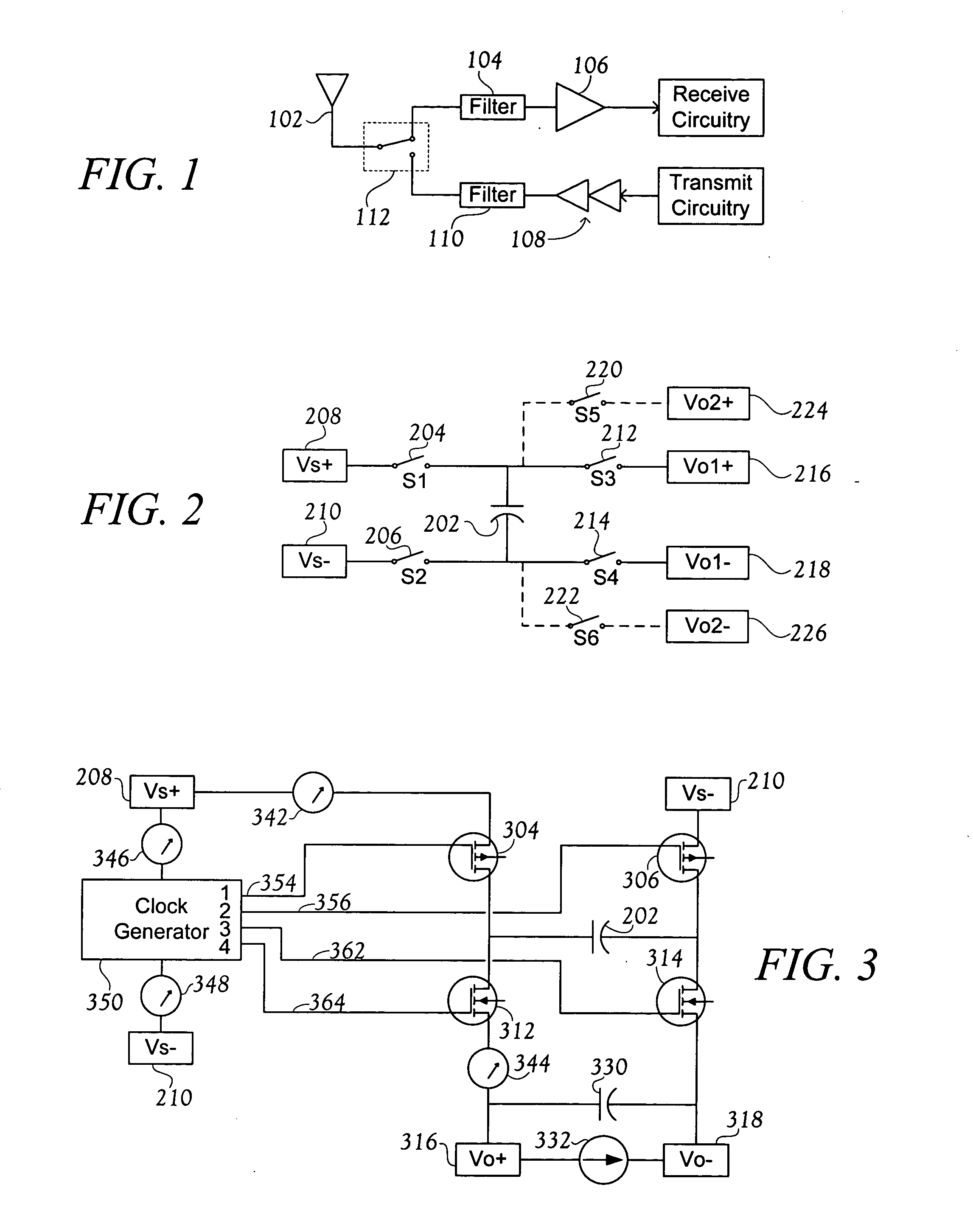
[0034]FIG. 2 illustrates some basic charge pump operations. Filtering capacitors, typically present on each input and output supply, are omitted from FIG. 2 to avoid confusion with an energy transfer capacitor CT 202. When S1204 and S2206 are closed, CT 202 is connected to the source DC supply connections VS+ 208 and VS−210, and thus CT 202 is charged to the voltage VS, having a value [(Vs+)−(Vs−)]. S1204 and S2206 are then opened, permitting CT 202 to float. Next, S3212 and S4214 are closed, causing the floating transfer capacitor CT 202 to “fly” to the output supply (for which reason such capacitors are also called fly capacitors). The charged CT is thus connected to output supply connections Vo1+ 216 and Vo1−218 (output Vo1). Presuming that the voltage of output Vo1 is smaller than the voltage stored on CT 202, CT 202 discharges, transferring energy to Vo1, which may be an output supply.

[0035] Many different output configurations are po...


PUM


Abstract

A charge pump method and apparatus is described having various aspects. Noise injection from a charge pump to other circuits may be reduced by limiting both positive and negative clock transition rates, as well as by limiting drive currents within clock generator driver circuits, and also by increasing a control node AC impedance of certain transfer capacitor coupling switches. A single-phase clock may be used to control as many as all active switches within a charge pump, and capacitive coupling may simplify biasing and timing for clock signals controlling transfer capacitor coupling switches. Any combination of such aspects of the method or apparatus may be employed to quiet and / or simplify charge pump designs over a wide range of charge pump architectures.

Description

BACKGROUND OF THE INVENTION [0001] 1. Field of the Invention [0002] This invention generally relates to electronic power supplies, and more specifically to capacitive energy transfer DC-to-DC converters (DC / DC converters), such as charge pumps. [0003] 2. Related Art [0004] DC / DC converter power supply circuits provide a DC output voltage based upon a DC source voltage. The output is typically at a different voltage than the input. As the term is used herein, DC / DC converters do not encompass voltage reduction regulator circuits that use a linear pass device, but rather involve energy transfer from input to output through an energy storage device, such as a capacitor or an inductor. [0005] The DC / DC converters of interest herein are charge pumps, which obtain energy for the output voltage primarily by means of capacitive transfer from the source to the output. An inductor is not generally the primary energy transfer device in a charge pump, though of course hybrid devices are possibl...

Claims


Application Information

Patent Timeline
Patent Type & Authority Applications(United States)
IPC IPC(8): H02M3/07
CPCH02M3/07H02M3/073H03K3/013H03K3/0315
Inventor BURGENER, MARK L.KELLY, DYLANCABLE, JAMES S.
Owner PSEMI CORP
Why Eureka
Try Eureka