Radio communication apparatus

a technology of radio communication and communication apparatus, which is applied in the direction of phase-modulated carrier systems, wireless communication services, coding, etc., can solve the problems of increasing the size of information data transmitted, achieving the target error rate, and achieving reception error rates

Inactive Publication Date: 2005-03-10
FUJITSU LTD
View PDF5 Cites 114 Cited by
  • Summary
  • Abstract
  • Description
  • Claims
  • Application Information

AI Technical Summary

Benefits of technology

Accordingly, an object of the present invention is to prevent a decline in throughput even under conditions where reception quality fluctuates widely owing to high-speed travel of a mobile station or a reception-quality reporting period that is too long.
Another object of the present invention is to prevent a decline in throughput by varying the target error rate in dependence upon the state of communication of a mobile station.
In accordance with the present invention, it is possible to prevent a decline in throughput, by varying the target error rate, even under conditions where reception quality fluctuates widely owing to high-speed travel of a mobile station or a reception-quality reporting period that is too long. That is, in accordance with the present invention, a variation-with-time characteristic of reception quality from the moment a mobile station measures reception quality to the moment a packet is actually received is estimated, and the target error rate is changed over adaptively based upon the variation-with-time characteristic in such a manner that throughput is maximized. As a result, a decline in throughput can be prevented.
In accordance with the present invention, a small target error rate is set if the variation in reception quality is small and a large target error rate is set if the variation in reception quality is large, whereby the target error rate is changed over adaptively. The reason for this is that if the target error rate is enlarged when the variation in reception quality is large, then, even though the error rate may deteriorate somewhat, it becomes possible to enlarge the size of the transmit data correspondingly and, hence, throughput can be improved. It should be noted that since recovery from a degraded packet error rate can be achieved by retransmission control, such degradation is not a major problem. This means that in a case where a plurality of mobile stations that travel at various speeds are present in a radio cell, a major improvement in throughput is achieved in comparison with the prior art.

Problems solved by technology

If the MCS increases, the size of the information data transmitted increases but, on the other hand, so does the reception error rate.
As a result, the target error rate can be met even if the reception quality of the radio downlink varies.
In the prior art, therefore, a problem which arises is that throughput declines under conditions where a target error rate set in advance is not always the optimum target error rate.
This leads to a decrease in transmit data quantity and a decline in throughput.

Method used


Image

  • Radio communication apparatus
  • Radio communication apparatus
  • Radio communication apparatus

Examples


first embodiment

(B) First Embodiment

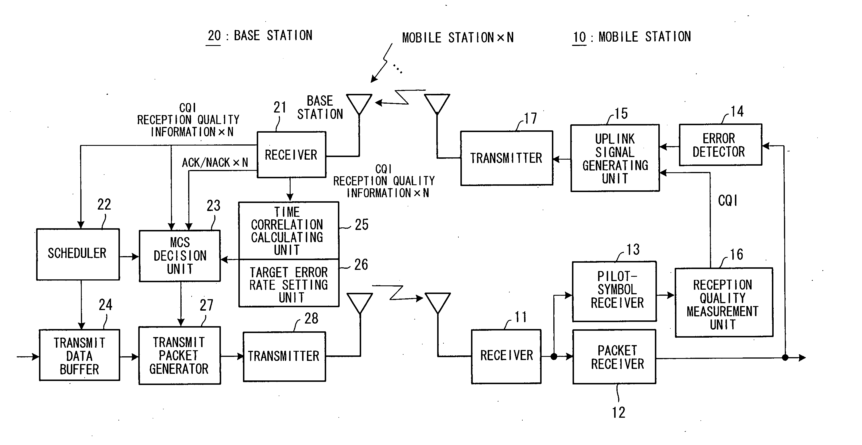
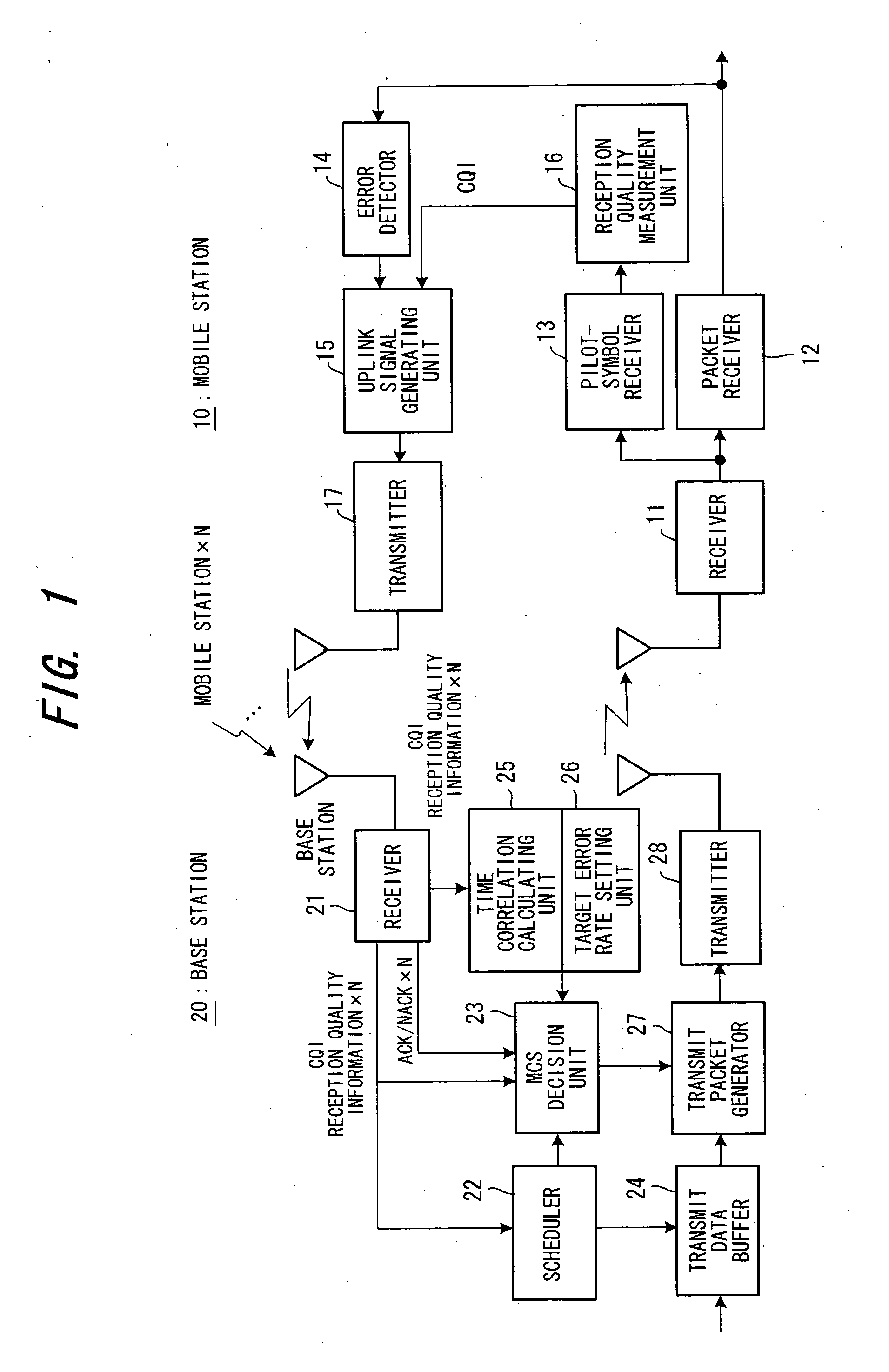
FIG. 1 is a block diagram illustrating the configuration of a radio packet communication system according to a first embodiment of the present invention.

As shown in FIG. 1, a mobile station 10 has a receiver 11 for receiving a high-frequency signal sent to it from a radio base station 20, converting the signal to a baseband signal and inputting the baseband signal to a packet receiver 12 and pilot-symbol receiver 13. The packet receiver 12 demodulates encoded packet data, applies decode processing and inputs the decoded signal to an error detector 14. The latter performs error detection using an error detecting code (CRC code) contained in the decoded signal and inputs the result of detection to an uplink signal generating unit 15. Meanwhile, the pilot-symbol receiver 13 extracts a pilot symbol and inputs the symbol to a reception quality measurement unit 16. The latter measures the SIR (Signal to Interference Ratio) as the reception quality of the radio downli...

second embodiment

(C) Second Embodiment

FIG. 3 is a block diagram illustrating the configuration of a radio packet communication system according to a second embodiment of the present invention, in which components identical with those of the first embodiment are designated by like reference characters. This embodiment differs only in the method of calculating the time correlation and the method of setting the target error rate and is the same as the first embodiment in other respects.

A time correlation calculating unit 31 obtains a time correlation value R2 of the downlink reception quality information in accordance with the following equation: R2=〈Re⁡[s⁡(t+τ)*⁢s⁡(t)]〉〈s⁡(t)2〉(6)

and inputs the value R2 to a target error rate setting unit 32. In Equation (6), s(t) represents a complex uplink pilot symbol that prevails after pilot pattern cancellation, t a time interval at which the time correlation is acquired, Re[ ] a function for taking the real part of a complex signal, and <X> the average...

third embodiment

(D) Third Embodiment

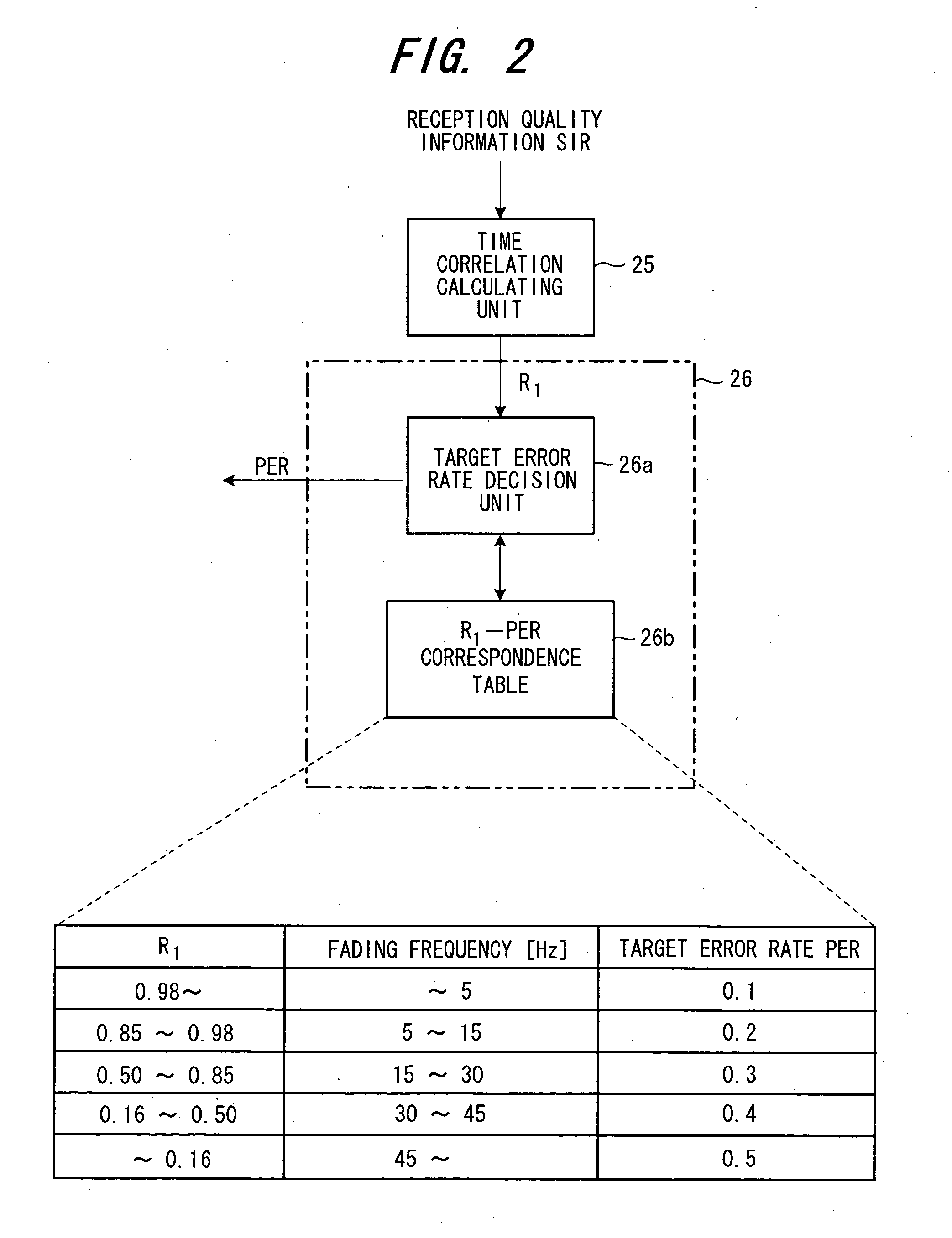
In radio communication, signals from a transmitter are reflected, diffracted and scattered by objects in the vicinity of the receiver, resulting in a multiplexed propagation path. A large number of waves that arrive at the vicinity of the receiver from various directions interfere with one another so that a random standing-wave electromagnetic distribution is formed. When a mobile station travels through such an electromagnetic distribution, a phenomenon referred to as fading, in which the amplitude and phase of received waves fluctuate randomly, occurs. In an ideal fading environment, the time correlation values R1, R2 in Equations (5), (6) and the fading frequency fD decided by the travelling speed of the mobile station are related as indicated by the following Equations (7), (8), respectively:

R1={J0(2πfDτ)}2  (7)

R2=J0(2πfDτ)  (8)

where fD represents the fading frequency [Hz], τ the time interval of the correlation, and J0(X) a Bessel function of degree 0. ...


PUM


Abstract

A base station has a time correlation calculating unit for estimating a variation-with-time characteristic of radio link quality using radio downlink quality information reported by a mobile station, a target error rate setting unit for changing over a target error rate adaptively using this variation-with-time characteristic, and an MCS decision unit for deciding a modulation scheme and / or encoding rate, in such a manner that packet error rate becomes equal to the target error rate, using the radio link quality information as well as reception success / failure information reported by the mobile station. The base station transmits a packet based upon the modulation scheme and / or encoding rate decided.

Description

BACKGROUND OF THE INVENTION This invention relates to a radio communication apparatus and, more particularly, to a radio communication apparatus in a radio packet communication system for feeding back radio link quality information, which has been measured on a packet receiving side, to a transmitting side and adaptively controlling the modulation scheme and / or encoding rate on the transmitting side using the quality information. In a radio packet communication system that uses adaptive modulation / demodulation and adaptive encoding such as High-Speed Downlink Packet Access (HSDPA) or High Data Rate (HDR), reception quality is measured from an already known downlink pilot symbol and is reported to the base station. On the basis of the reported value, the base station changes the encoding rate and modulation scheme (a combination of encoding rate and modulation scheme shall be referred to below as a modulation and coding scheme, or “MCS”) and then transmits the downlink packet, ther...

Claims


Application Information

Patent Timeline
Patent Type & Authority Applications(United States)
IPC IPC(8): H04L27/18H04L1/00H04L1/16H04L27/00H04L27/34H04L29/08H04W28/00H04W28/18
CPCH04L1/0003H04L1/0009H04L1/1671H04L1/0021H04L1/0034H04L1/0016
Inventor KIMURA, DAI
Owner FUJITSU LTD
Why Eureka
Try Eureka