
All optical variable buffer queue useful in optical packet networks

a buffer queue and optical variable technology, applied in multiplex communication, electrical equipment, wavelength-division multiplex systems, etc., can solve the problems of difficult scaling of electronic routers in wdm networks to a large number, difficulty in implementing optical memory, and especially random access optical memory

Inactive Publication Date: 2005-03-10
RGT UNIV OF CALIFORNIA
View PDF12 Cites 35 Cited by
  • Summary
  • Abstract
  • Description
  • Claims
  • Application Information

AI Technical Summary

Problems solved by technology

Combining these advances has presented difficulties.
Electronic routers in WDM networks are difficult to scale to a large number of channels and present other problems of carrying different types of traffic on a large network.
A principal problem with optical routers is the difficulty of implementing optical memory, particularly random access optical memory.
A feedback fiber of substantial length can be installed from the output side to the input side of the router to provide a fixed delay storage, but the feedback route complicates the router control and may contribute to further delay.
However, such an arrangement splits the optical power and requires bulky fibers.

Method used


Image

  • All optical variable buffer queue useful in optical packet networks
  • All optical variable buffer queue useful in optical packet networks
  • All optical variable buffer queue useful in optical packet networks

Examples


Embodiment Construction

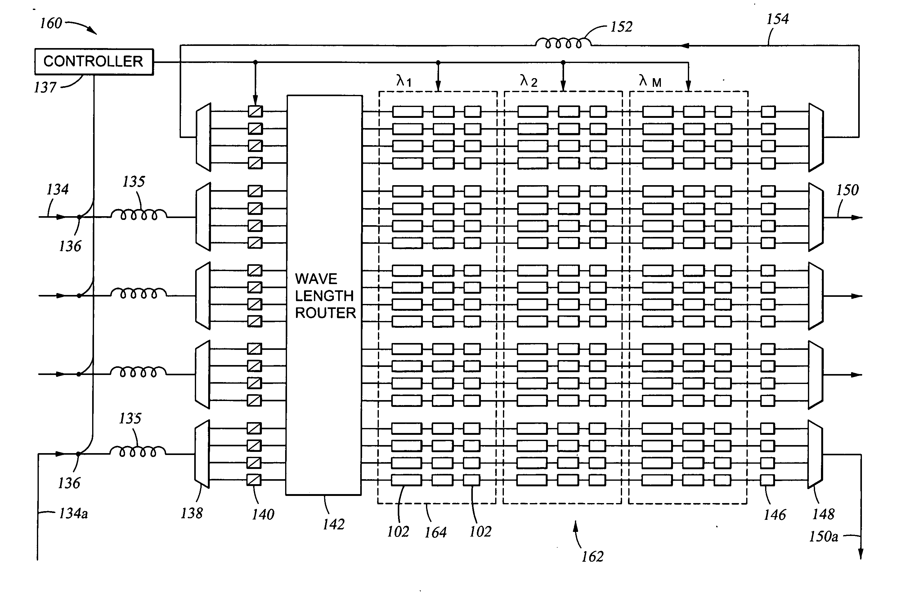
[0024] Packet loss at an optical router may be greatly reduced by including controllable optical buffers either on the input side of the router or on the output side or on both sides, thus providing a controllable queuing function to the router, either from the input fiber into the optical router or from the optical router to the output fiber.

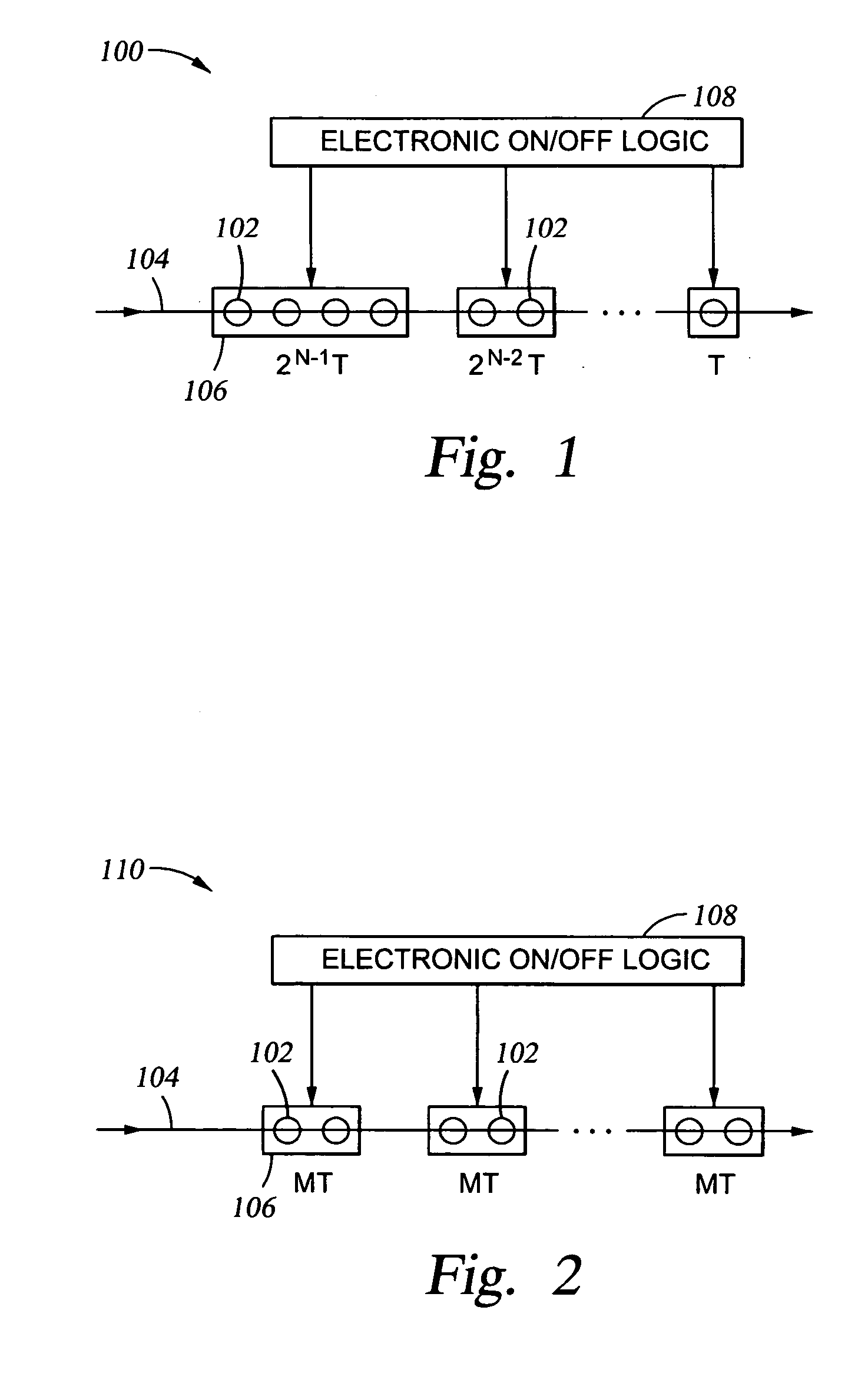
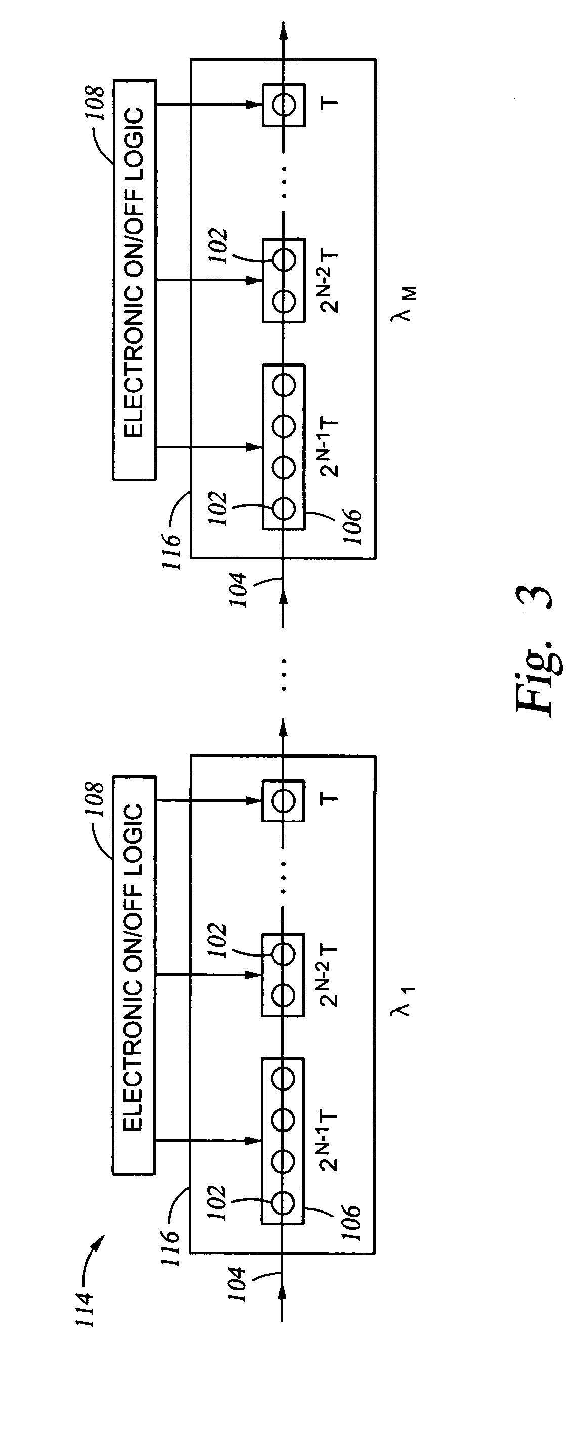
[0025] Although the invention is not so limited, one type of optical buffer is a variable all-optical unit 100 illustrated schematically in FIG. 1. It includes a series of microresonators 102 arranged along an optical waveguide 104 and grouped in N exponentially sized delay components 106 serially connected along the waveguide 104. Each delay component 106 contains 2M serially connected microresonators 102, where M increases from 0 to (N−1) for the N delay components 106. An electronic on / off logic 108 electronically tunes the resonances of the microresonators 102 to vary the finesse F of the resonant microcavities. The value of the finesse F ...


PUM


Abstract

A variable optical buffer queue, particularly useful either as an input or an output queue in an optical packet router in a wavelength-division multiplexing (WDM) communication network. An input queue includes plural separately controllable optical delay units disposed on wavelength channels between a demultiplexer and tunable wavelength converters controlling switching through a wavelength router. An output queue includes for each output port of a wavelength router plural separately controllable optical delay units tuned to different wavelengths. The delay units may induce selective amounts of delay and may be implemented as a series of controlled microresonators coupled to waveguide. Such a structure is usable as a controllably accessible optical memory.

Description

RELATED APPLICATION [0001] This application claims benefit under 35 U.S.C. §119 of provisional application 60 / 500,406, filed Sep. 4, 2003, which is incorporated herein by reference in its entirety.BACKGROUND OF THE INVENTION [0002] 1. Field of the Invention [0003] The invention relates generally to switches used in optical communications networks. In particular, it relates to optical routers and optical buffers used therein. [0004] 2. Background Art [0005] Two important recent advances in communication networks include large, high-capacity networks based on packet switching and optical fiber transmission media, in particular silica fiber. More recent further advances include asynchronous packet switching, such as the TCP / IP protocol of Internet networks, and wavelength-division multiplexing (WDM) of multiple optical signals on a single fiber. Combining these advances has presented difficulties. [0006] Heretofore, the switching of asynchronous packets has been typically performed by ...

Claims


Application Information

Patent Timeline
Patent Type & Authority Applications(United States)
IPC IPC(8): H04J14/02H04Q11/00
CPCH04J14/02H04Q2011/002H04Q11/0005
Inventor YOO, SUNGJOO BENYANG, HAIJUN
Owner RGT UNIV OF CALIFORNIA
Learn More