Tracking clutter filter for spectral & audio doppler

a technology of spectral and audio dopplers, applied in tomography, instruments, and reradiation, etc., can solve the problems of more difficult implementation of adaptive clutter filters in spectral dopplers, noise signals, and wall thumping in audio speakers

Inactive Publication Date: 2005-03-10
KONINKLIJKE PHILIPS ELECTRONICS NV
View PDF27 Cites 42 Cited by
  • Summary
  • Abstract
  • Description
  • Claims
  • Application Information

AI Technical Summary

Benefits of technology

[0018] The present invention provides a method and system for adaptively filtering the clutter from an incoming signal in an ultrasound system in spectral Doppler imaging mode. In the inventive system and method, the stopband of the cl...

Problems solved by technology

Specifically, the unwanted strong and slow signals create clutter signals (high-amplitude spikes in the time-velocity spectrum) and “wall thump” in the audio speakers.
By contrast, implementing an adaptive clutter filter in spectral Doppler is more challenging.
Moving clutter signals are annoying when performing spectral Doppler imaging.
Because an adaptive clutter filter is not available for ultrasound systems in spectral Doppler imaging mode, the operator typically manually increases the cutoff frequency of the clutter filter (i.e., widens the stopband) when moving clutter begins to show up as bright (high amplitude), low (low frequency) signals in the time-velocity spectral display.
However, if the clutter filter stopband is coarsely manipulated by operator manual control in order to eliminate the systolic clutter thump, then the slo...

Method used


Image

  • Tracking clutter filter for spectral & audio doppler
  • Tracking clutter filter for spectral & audio doppler
  • Tracking clutter filter for spectral & audio doppler

Examples


Embodiment Construction

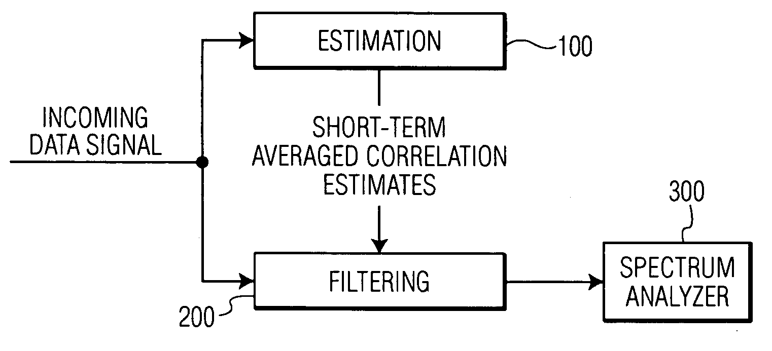
[0028] As stated above, the present invention is directed to an adaptive clutter filter with two basic components, as shown in FIG. 3: the estimation 100 of the clutter frequency and the filtering 200 of the incoming signal before entering the spectrum analyzer 300. It should be understood that these three modules are conceptual, and do not limit the manner of implementing the present invention in any way, i.e., the functions shown herein being performed in these modules may be performed by any combination of hardware, software, or firmware. Furthermore, the functions in one module may be performed by another, or combined together in a single module.

[0029] During estimation 100, instantaneous correlation estimates are formed and then averaged over a short period to produce average short-term correlation estimates. The specific components of Estimation 100 are shown in FIG. 4. Estimation 100 may include a low-pass filter (LPF) 110 which will filter the time-domain data signal so tha...


PUM


Abstract

In an adaptive clutter filter for spectral Doppler imaging using an ultrasound system, the stopband center frequency and/or bandwidth of the clutter filter are effectively adjusted on a short time scale to better eliminate moving clutter while allowing low velocity bloodflow signals to pass through.

Description

CROSS REFERENCE TO RELATED CASES [0001] Applicant claims the benefit of Provisional U.S. Application Ser. No. 60 / 501,529, filed Sep. 09, 2003.FIELD OF THE INVENTION [0002] This invention relates to ultrasonic imaging systems and, in particular, to the elimination of clutter from echo signals received by an ultrasonic system in spectral Doppler imaging mode. DESCRIPTION OF THE RELATED ART [0003] Ultrasonic medical transducers are used to observe the internal organs of a patient. The ultrasonic range is described essentially by its lower limit: 20 kHz, roughly the highest frequency a human can hear. The medical transducers emit ultrasonic pulses which, if not absorbed, echo (i.e., reflect), refract, or are scattered by structures in the body. Most of the received signal is from scattering, which is caused by many small inhomogeneities (much smaller than a wavelength) making a small part of the wave energy disperse in all directions. The signals are received by the transducer and these...

Claims


Application Information

Patent Timeline
IPC IPC(8): A61B8/06G01S15/89
CPCG01S15/8981A61B8/06
Inventor CLARK, DAVID W.
Owner KONINKLIJKE PHILIPS ELECTRONICS NV
Why Eureka
Try Eureka