Numerically controlled curved surface machining unit

a machining unit and numerical control technology, applied in the direction of electric programme control, program control, instruments, etc., can solve the problem of not having a means for smoothly changing the two nurbs curves, and achieve the effect of reducing burden, reducing the speed of load change in the servo mechanism, and reducing the behavior

Inactive Publication Date: 2005-03-10
HITACHI LTD +1
View PDF10 Cites 15 Cited by
  • Summary
  • Abstract
  • Description
  • Claims
  • Application Information

AI Technical Summary

Benefits of technology

As a result, the tool control point 64 in a tool attitude 63 to be required at a reversing position of the rotary axis becomes really a tool control point 66 in a tool attitude 65 by a rapid load change of the servo mechanism, which results in worsening in cutting into the material to be machined and / or machined surface roughness, shortening in machine tool life, and excessive burden on the numerically controlled curved-surface machining unit.
An object of the present invention is to provide a numerically controlled curved-surface machining unit which is provided with means for making no rapid angle change of an rotary axis and making the angle change smooth when NC data is formed by NURBS interpolation based on a tool moving locus or path of CL data produced in a CAM system.
According to the present invention, it is possible to reduce not only a rapid change in an optimum real feed rate and behavior of a tool (or tool tip) in a tool movement locus drawing a free curve, but a rapid change of behavior on linear (or straight) axes coordinates and rotary coordinates of a machine coordinate system, so that it is possible to perform extension of machining tool life, reduction of a rapid load change in a servo mechanism, reduction of burden on the numerically controlled curved-surface machining unit, improvement on roughness of machined surfaces and machining of curved-surfaces at high machined surface accuracy. As a result, hand-finishing man-hours in after procedures can be greatly reduced.

Problems solved by technology

However, any analysis about whether the sharp bend in tool control point behavior is caused by an operation due to NC data on the linear coordinate axes or operation on the rotary coordinate axis has not been conducted and there was no means for changing smoothly the two NURBS curves.

Method used


Image

  • Numerically controlled curved surface machining unit
  • Numerically controlled curved surface machining unit
  • Numerically controlled curved surface machining unit

Examples


embodiment 2

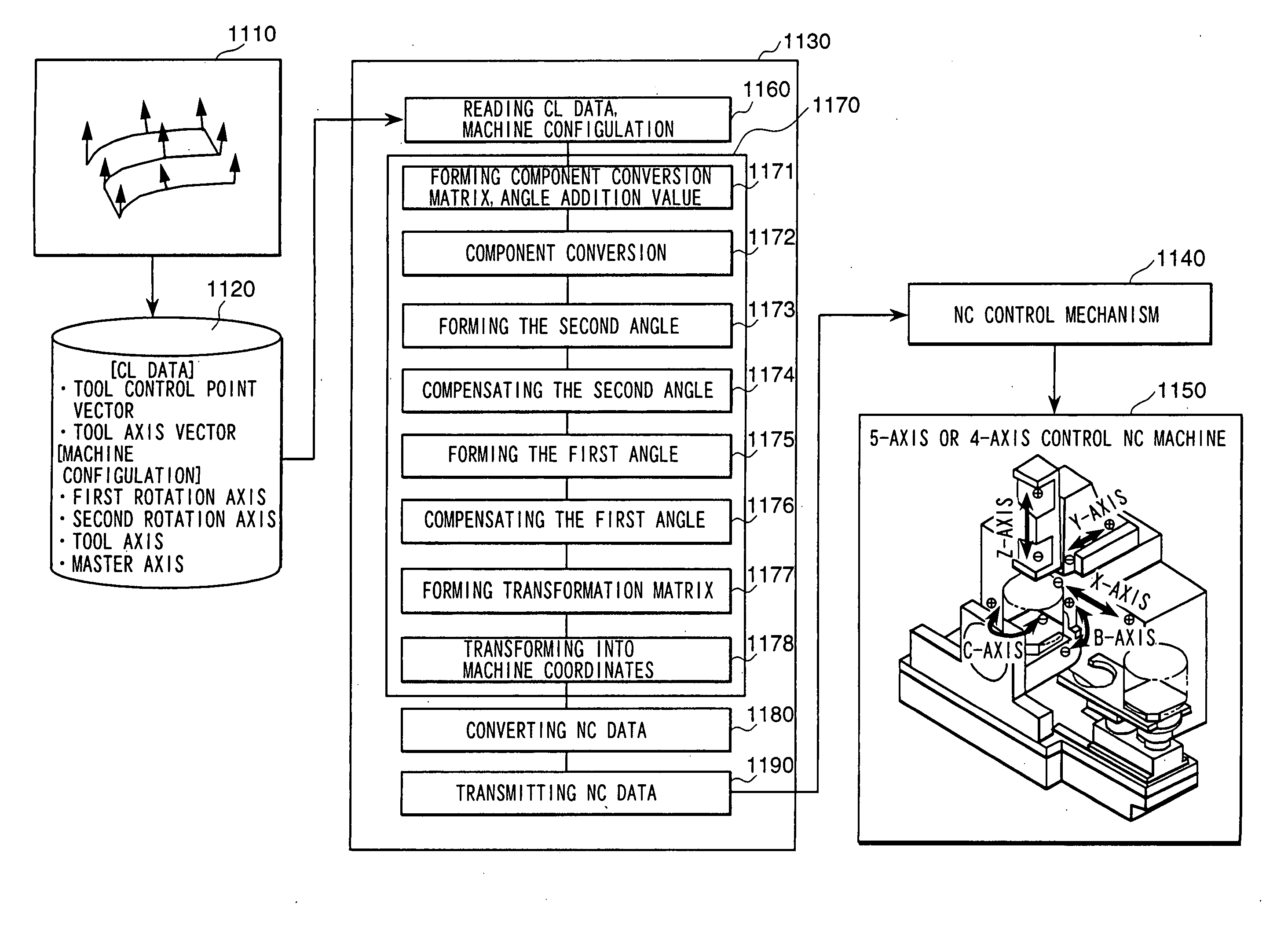
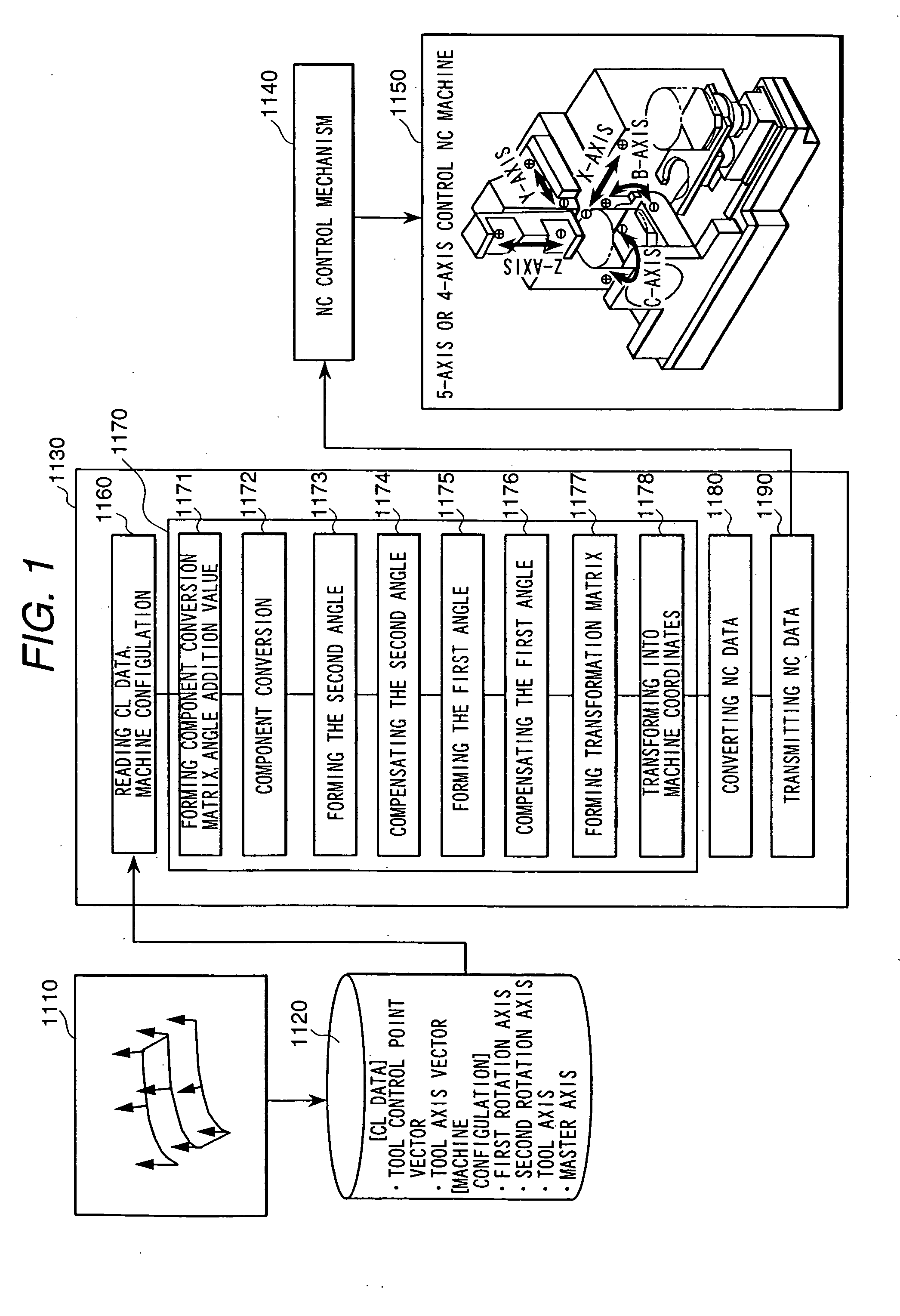
FIG. 5 is a block diagram showing a system configuration of a second embodiment of a numerically controlled curved surface machining unit according to the present invention.

The second embodiment is an embodiment in which the machine coordinate converting means of the numerically controlled curved-surface machining unit described in the previously mentioned US application or JP 2001-92516 is replaced by the coordinate converting means 1170 inside the post processor unit 1130 in FIG. 1.

Since the coordinate converting means 1170 can avoid a rapid change in angle by limit on computer installation, in the second embodiment also it is possible to prevent the phenomenon that each axis rapidly rotates at a high speed and the phenomenon that a tool moves to an unintended position and to perform such machining that tool breakage, machine breakage, too much cutting and too less cutting are less.

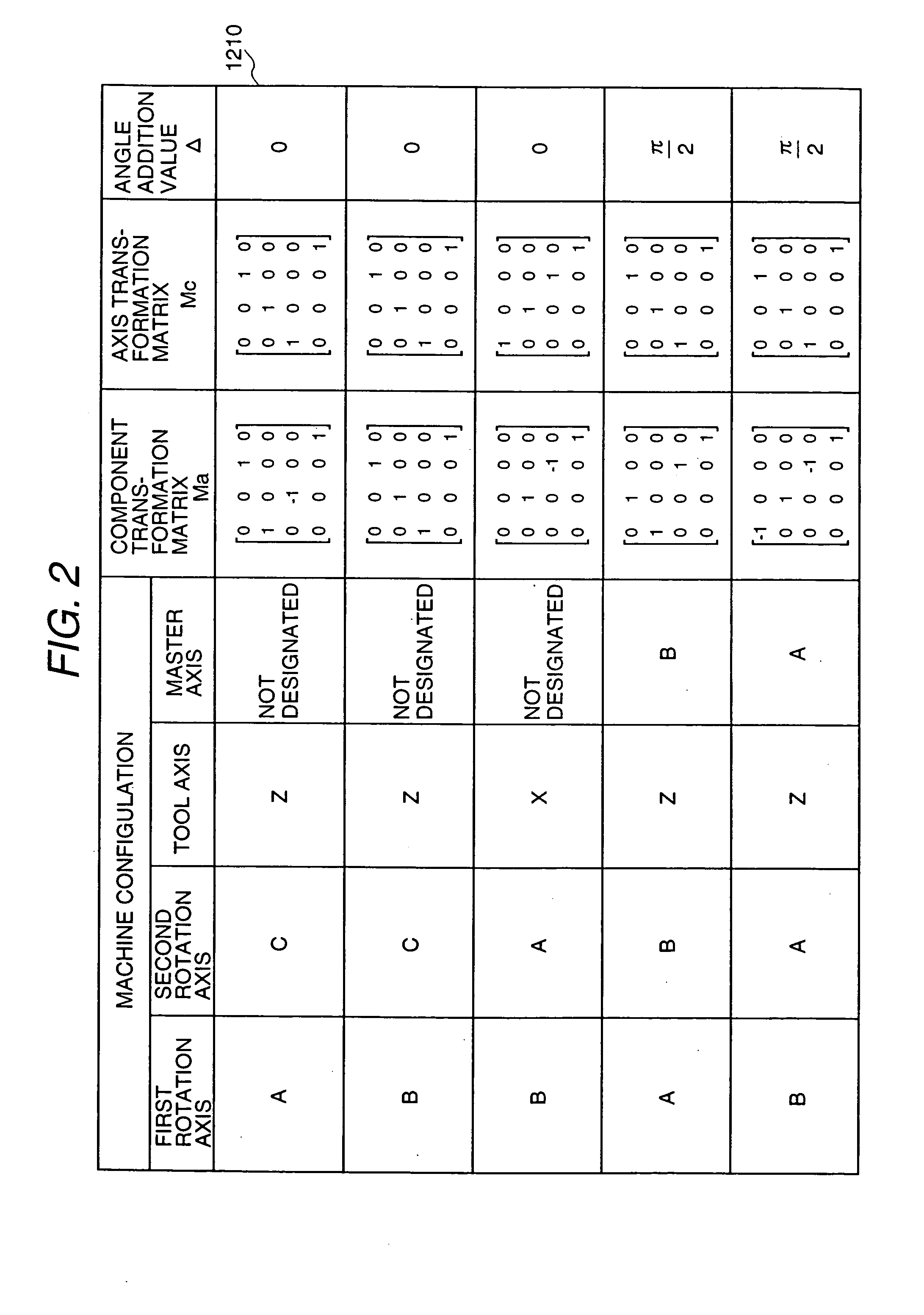
As for the means 1171 to 1190 of the machine coordinate converting means 1170 in the second em...


PUM


Abstract

A numerically controlled curved-surface machining unit comprises a component converting matrix•angle-addition value forming function of converting CL (cutter location) data into components on a normal coordinate system on the basis of the machine configuration of the simultaneous multiple-axis control NC machine, a component converting function of converting from the workpiece coordinate system to the normal coordinate system, a function of forming second angles of a second rotary axis on the normal coordinate system, a compensating function of forming a continuous angle distribution from a distribution of the second angles, a function of forming first angles of a first rotary axis on a coordinate system rotated by the second angles at the second rotary axis, a compensating function of forming a continuous angle distribution from a distribution of the first angles, a machine coordinate transformation matrix forming function of obtaining a matrix for converting the tool control point vectors on the workpiece coordinate system into a machine coordinate system by using the first angles and the second angles, and a machine coordinate converting function of converting the tool control point vectors into the machine coordinate system by using the machine coordinate transforming matrix.

Description

BACKGROUND OF THE INVENTION 1. Field of Utilization in Industry The present invention relates to a numerically controlled curved surface machining unit and, particularly to such a unit that improves machining surface roughness and accuracy and enables to achieve high-speed machining. 2. Description of Prior Art FIG. 10 shows comparison between a conventional linear interpolation machining method and a conventional NURBS interpolation machining method. In conventional NC (numerically controlled) curved-surface machining, as shown in FIG. 10(a), it is machined by broken-line approximation, so that the machined surface roughness is bad and a lot of hand-finishing steps are needed thereafter. Further, as shown in FIG. 10(b), by acceleration / deceleration when positioning, an average feed rate decreases, as a result, a long machining time is needed, further, a vast amount of NC (numerical control) data at shorter pitches are required to improve the machining surface accuracy. Then, f...

Claims


Application Information

Patent Timeline
Patent Type & Authority Applications(United States)
IPC IPC(8): G05B19/4099G05B19/4103
CPCG05B19/4099G05B2219/34141G05B19/4103
Inventor HIRAI, JUNICHIARAI, HIROSHIHARIHARA, TAMOTSUCHIBA, OSAMUTAKAHASHI, MASAAKIKANAMARU, NOBUHISA
Owner HITACHI LTD
Why Eureka
Try Eureka