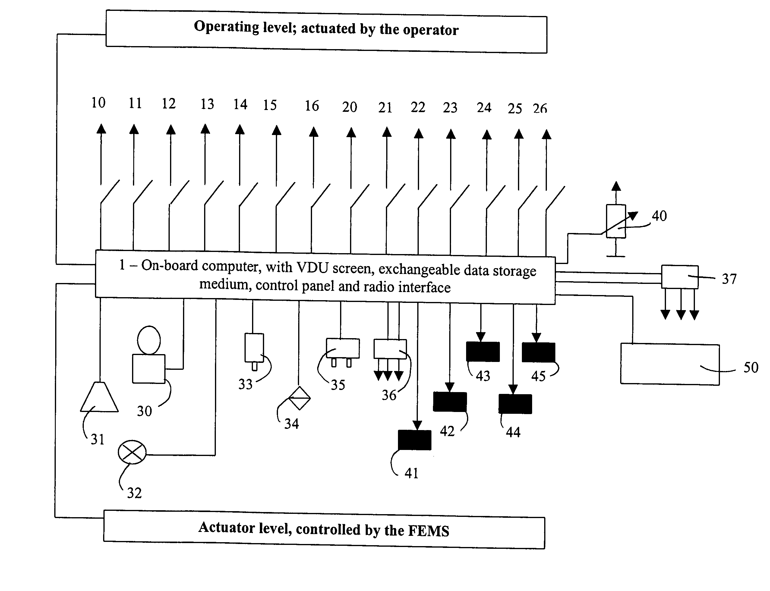
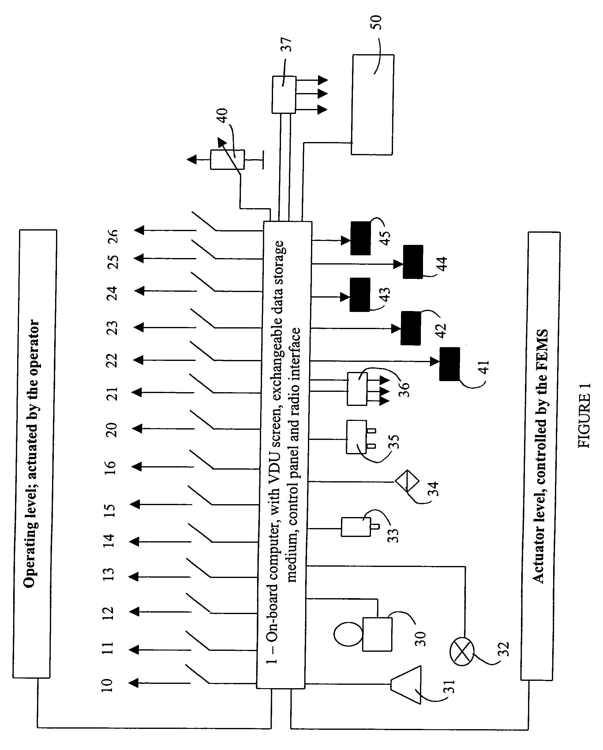
[0015] According to the invention, by means of the above equipment, devices, sensors and installations all the data for the
route, manner of driving and mode of working of the agricultural utility vehicle including the coupled load or of a coupled mounted implement, time- and / or path- and / or position- and / or event-relevant data are stored, evaluated and if necessary displayed in a timed sequence. The appropriate implied
software in the on-board computer recognizes repeated drive management events, displays these in timed mode if required and stores all the necessary driving-relevant data. Therefore this drive management can be performed repeatedly automatically or partially automatically. At the same time the individual functions of the
management system are invocable and switchable by the operator as a whole or in driving blocks and / or in timed, independent steps. Individual items of the driving management can if necessary be ignored by the operator. For reasons of safety drive management independent of a possible
initiation by the operator in public traffic space is blocked, so that no operating errors at all are possible. During the trip the agricultural utility vehicle automatically recognizes via the drive
management system movable or unforeseen fixed obstacles (persons, animals, masts, stones, trees or other objects) and deactivates the drive
management system immediately or with a
delay. If the operator does not intervene, the agricultural utility vehicle comes to a standstill. Regardless of this situation, the operator's attention is constantly monitored and the vehicle comes to a standstill automatically, if the operator does not react. Such monitoring functions can be performed in a kind of dead man'
s function, as is usual e.g. on the railways. In other forms of implementation, eye movements, the
gaze position or the frequency of blinks of the eyelids can be monitored by means of suitable sensors and from this conclusions can be drawn regarding the driver's attention. Through this, damage to the very expensive machinery of the agricultural utility vehicle can reliably be avoided.
[0018] Especially at the field end, on automatic recognition of obstacles, the drive management
system is deactivated immediately or after time
delay in order to avoid damage. Thus it is programmable, that, for example, in the event of movable obstacles being encountered, the agricultural utility vehicle immediately comes to a standstill, while in the case of fixed obstacles these are first displayed and only after further approach, if in the meantime no reaction of the operator has occurred, it comes to a standstill. The operating facility of an emergency pushbutton for immediate disabling of the drive and / or field end management systems is advantageous.
[0022] In this way it is possible for the first time to optimize the drive and / or field-end management
system in accordance with different criteria depending upon the operation in question, and environmental and weather conditions. Handling by the operator is simplified, as in the first instance it takes over a monitoring function. Possible operating errors are recognized in advance and can be avoided. Damage to the relevant machinery is minimized.
[0024] In a further embodiment in the process for controlling an agricultural utility vehicle, when
programming in the computer independent of the utility vehicle and / or the on-board computer instead of a virtual expanse a virtual grid is laid out over the relevant non-public, agriculturally exploited area. When doing so, the grid lines serve as the basis for controlling the drive management and / or field-end management depending upon the employed agricultural utility vehicle and its coupled load and / or mounted implement. The outermost lines are used at the same time as boundary lines, which may not be run over by the agricultural utility vehicle in automatic operation. This means increased protection of sensitive machinery. Through the
subdivision of the area into individual grid fields, also individual grid fields or entire grid regions can be defined, where the automatic drive management and / or field-end management can be put out of action or, if necessary, alterations can be implemented in the field-end
management functions. Thus, if within the area to be treated, obstacles, such as a body of water, stony ridges, hedge rows, single trees or groups of trees, exist, or in sloping areas, the speed can be reduced or, for example, for particular
soil quality (little
topsoil, then very stony beneath it), the coupled
processing implement can be raised. This virtual grid opens up for the first time the possibility, even for very extensive agriculturally exploited areas, which are subdivided by or covered with so-called
erosion protective plantings, that an economical drive management and / or field-end management
system can be employed for the entire area. The individual lines of the grid can also run in curves. Finally through changing of the
grid pattern there is no problem in adapting the control in accordance with the given conditions for the agriculturally exploited area. Suitable methods for the
simulation are manageable on a computer with, for example, the
finite element method. Furthermore, lines
lying within the grid can be used for
automatic control of the drive management and / or field end management system, in that on driving over them appropriate functions and / or actions of the agricultural utility vehicle including the coupled load and or the mounted implement are triggered. The individual grid intersections can if necessary be used for adjustment of the actual position via the GPS, so that the GPS system does not have to be in constant use.

