Dowels and methods for the assembly of insulating panels

a technology of insulating panels and dowels, which is applied in the field of dowels, can solve the problems of considerable abrasion of insulating materials, undesirable dowel show-through in the plaster layer at the outer walls, and inability to completely prevent the formation of thermal bridges, so as to avoid the pollution of the environment by milling insulating materials

Active Publication Date: 2005-03-17
EJOT GMBH & CO KB
View PDF13 Cites 15 Cited by
  • Summary
  • Abstract
  • Description
  • Claims
  • Application Information

AI Technical Summary

Benefits of technology

[0007] It is the object of the invention to provide a dowel, a process and further devices, by means of which the pollution of the environment by milling the insulating material can be avoided, a recessed mounting of the dowel in the insulating material with as few pr

Problems solved by technology

Conventional dowels for mounting insulating plates have the disadvantage, that they cannot entirely prevent the formation of thermal bridges, which also applies for dowels having a plastic coat or heads made of plastic.
This diversity may also lead to undesirable dowel show-through in the plaster layer at the outer walls, especially when exposed to moisture and wetness.
This disadvantage occurs frequently when applying basic plaster qualities.
However, the milling leads to a considerable abrasion of insulating material.
Considering the large number of dowels which are regularly used for mounting insulating plates when building a house, the generated milling dust poses a considerable pollution of the environment, and, in larger amounts, may also lead to health problems for the construction personnel.
Further, the mounting properties of dowels having coverings applied at the factory are clearly inferior to comparable dowels without applied covering.
Due to the insufficient resistance to pressure of the insulating material and the thus

Method used


Image

  • Dowels and methods for the assembly of insulating panels
  • Dowels and methods for the assembly of insulating panels
  • Dowels and methods for the assembly of insulating panels

Examples


Embodiment Construction

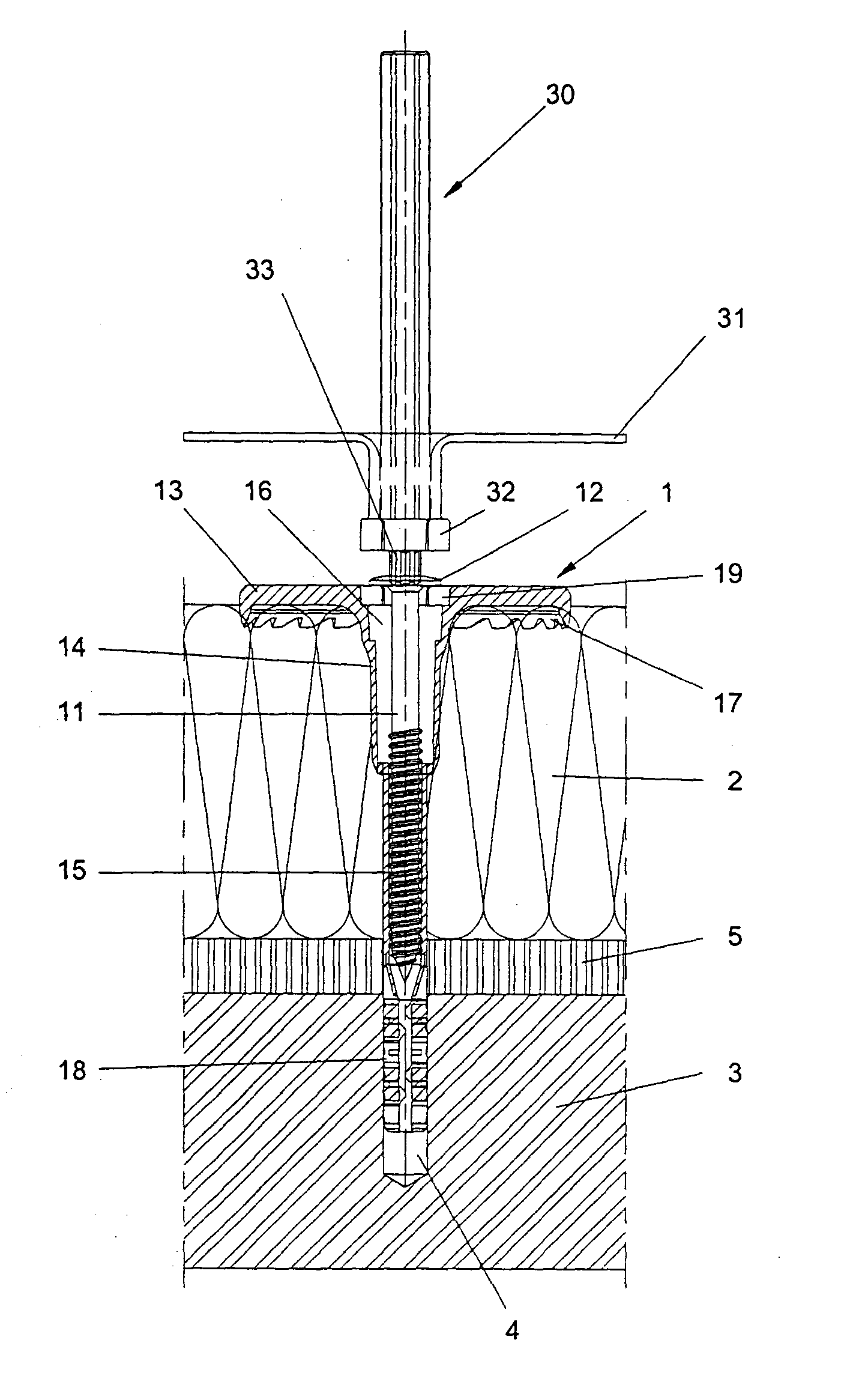
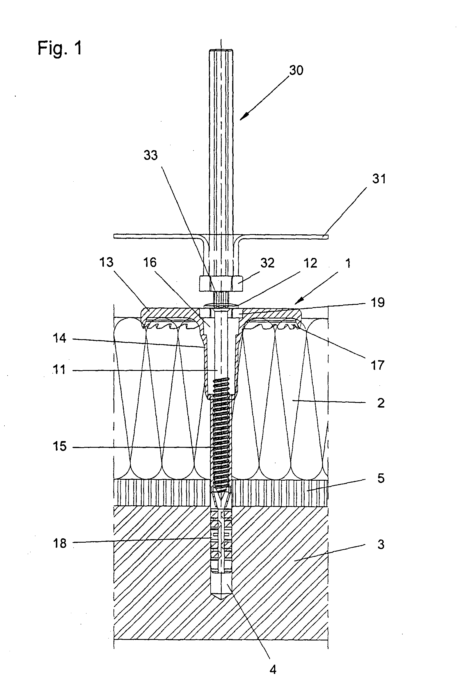
[0034]FIG. 1 shows the dowel 1 which has already been put through an insulating plate 2 and an intermediate layer 5 into the brickwork 3. The pressing plate shaft 14 and the dowel sleeve 15 are connected with each other in this state, for inserting the dowel in full length. The pressing plate 13 which is provided at its lower side with radial cutting devices 17, lies on the surface of the insulating plate 2, wherein the cutting devices 17 are stuck in the insulating material. The pressing plate 13 is usually provided with co-axially arranged openings, however, regarding compressing the insulating material as uniformly as possible, also embodiments without openings are conceivable. The expansion element 11, preferably an inside torx screw in this case, has been inserted into the dowel sleeve 15 up to the expansion zone 18 by means of a respective drive 32, 33, so that the expansion element head 12 does not yet bear on the recess 16. The expansion element 11 can be realized without pl...


PUM

PropertyMeasurementUnit
Digital informationaaaaaaaaaa
Depthaaaaaaaaaa

Abstract

The invention relates to a dowel having cutting devices at the lower side of the pressing plate at the circumference of said pressing plate for cutting into the insulating panel when the pressing plate is pulled into the insulating panel. The invention further relates to a method, in which a bore-hole is drilled through the insulating panel into the substructure, the dowel and the expansion element are inserted into the bore-hole, the expansion element is driven into the pressing plate and the dowel sleeve, and wherein simultaneously the pressing plate is pulled into the insulating panel under compression of the insulating panel, and the insulating panel is cut in at the circumference of the pressing plate by means of cutting devices. The invention further relates to a method in which a bore-hole is drilled trough the insulating panel into the substructure, a circle with at least the radius R is cut into the insulating panel by means of cutting devices, the dowel and the expansion element are inserted into the bore-hole, the expansion element is driven into the pressing plate and the dowel sleeve, and simultaneously the pressing plate is pulled into the insulating panel under compression of the insulating panel.

Description

FIELD OF THE INVENTION [0001] The present invention relates to a dowel, a process and further to devices for mounting insulating plates on a substructure, wherein the dowel includes a pressing plate and a dowel sleeve attached to said pressing plate for taking up an expansion element having an expansion element head, wherein the dowel sleeve comprises an expansion zone, and wherein a recess is formed in the insulating plate by the dowel itself during mounting. BACKGROUND OF THE INVENTION [0002] Conventional dowels for mounting insulating plates have the disadvantage, that they cannot entirely prevent the formation of thermal bridges, which also applies for dowels having a plastic coat or heads made of plastic. Substantially, this results from the diversity of the materials of which the insulating material on the one hand and the dowel on the other hand are made. This diversity may also lead to undesirable dowel show-through in the plaster layer at the outer walls, especially when ex...

Claims


Application Information

Patent Timeline
IPC IPC(8): E04F13/08F16B13/00
CPCB23B49/005B23B51/0406B23B51/0426E04B1/7633E04F13/0835Y10T403/75Y10T29/49947Y10T29/49826Y10T29/49945Y10T29/49623F16B13/00B23B51/04
Inventor TIEMANN, JOACHIMHACKLER, ERHARDKNEBEL, ULRICH
Owner EJOT GMBH & CO KB
Why Eureka
Try Eureka