Engine control apparatus

a control apparatus and engine technology, applied in the direction of electrical control, process and machine control, instruments, etc., can solve the problems of unplanned fluctuations in the amount of nox discharged, lean nox catalysts may be diagnosed as having deteriorated, etc., to reduce storage capacity and improve the effect of emission gas performan

Inactive Publication Date: 2005-03-17
HITACHI LTD
View PDF5 Cites 11 Cited by
  • Summary
  • Abstract
  • Description
  • Claims
  • Application Information

AI Technical Summary

Benefits of technology

In the control apparatus of the present invention, when an unexpected fluctuation has occurred in the amount of NOx discharged from the combustion chamber due to insufficient combustibility of the engine, EGR error, deterioration or trouble, and an abnormal increase has occurred in the amount of NOx discharged downstream from lean NOx catalyst, then deterioration of lean NOx catalyst is considered to have taken place due to diagnostic error, according to the prior art. By contrast, the present invention eliminates the possibility of such diagnostic error because the performance of the lean NOx catalyst is diagnosed, with consideration given to the fluctuation in the amount of N

Problems solved by technology

To put it in greater details, unexpected fluctuations may occur to the amount of NOx discharged from the combustion chamber or the amount of NOx flowing into the lean NOx catalyst due to deterioration

Method used


Image

  • Engine control apparatus
  • Engine control apparatus
  • Engine control apparatus

Examples


embodiment 1

FIG. 30 is a schematic diagram representing the first embodiment of the present invention, together with an example of the car-mounted cylinder injection engine to which the same is applied.

A cylinder injection engine 10 is a multi-cylinder engine, and includes a cylinder 12 and a piston 15 inserted slidably in the cylinder 12. A combustion chamber 17 is formed over this piston 15. The combustion chamber 17 contains an ignition plug 35 and a fuel injection valve 30 that directly injects a fuel into the combustion chamber 17.

The fuel injection valve 30 is supplied with the fuel regulated to a predetermined pressure, by a fuel supply system equipped with a fuel tank, low pressure fuel pump, fuel pressure regulator and high pressure fuel pump (not illustrated).

Air supplied for combustion of fuel is taken inside by an air cleaner 21 installed on the starting end of an intake path 20, and is put into a collector 27 through an air flow sensor 24 and an electronically controlled thro...

embodiment 2

The following describes a second embodiment of the present invention: The system configuration of the second embodiment is approximately the same as that of the first embodiment (see FIGS. 30, 31, 32 and 33), and will not be described here to avoid duplication.

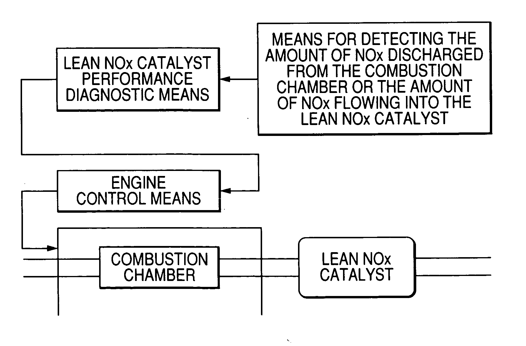
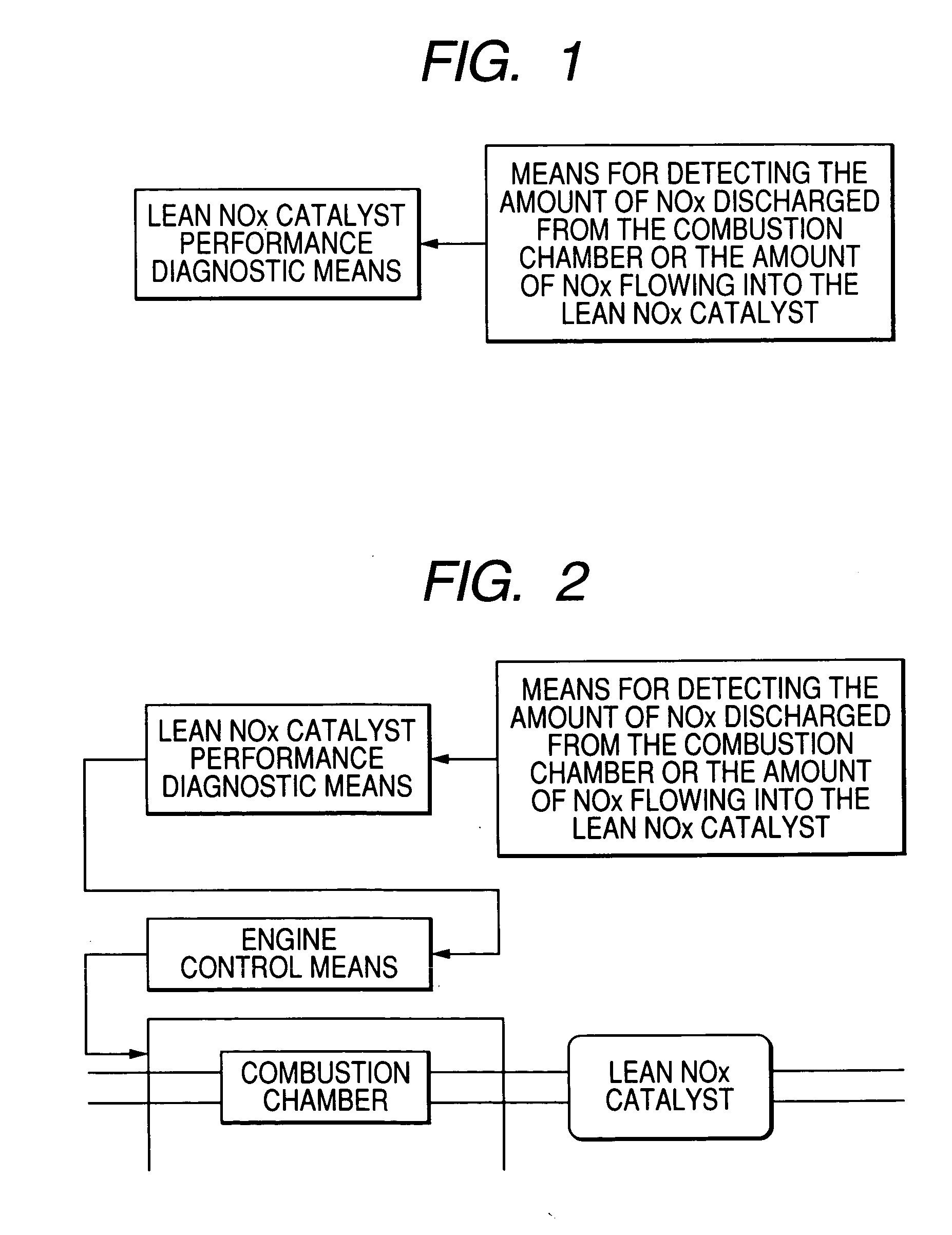
FIG. 42 is a block diagram showing the diagnostic section for the lean NOx catalyst and the amount of NOx discharged from the combustion chamber. This diagnostic section is the same as that of the first embodiment (FIG. 34), except for the calculation section for calculating the amount of stored NOx (executed in the rich operation mode). The calculation section for calculating the amount of stored NOx calculates the amount of stored NOx by detecting the concentration of the oxygen downstream from catalyst. As described above, the calculation section for calculating the amount (concentration) of NOx downstream from catalyst in the lean operation mode (executed in the lean operation mode), engine NOx emission volume model, lea...

embodiment 3

The following describes a third embodiment of the control apparatus of the present invention: The system configuration of the third embodiment is approximately the same as that of the first embodiment (see FIGS. 30 and 31), and will not be described here to avoid duplication.

FIG. 44 is a diagram showing a control system of the third embodiment, and corresponds to FIG. 32 showing the first embodiment. In the present embodiment, the lean NOx catalyst, the amount (reference value A) of NOx downstream from the lean NOx catalyst 50 calculated by the diagnostic section for diagnosing the amount of NOx discharged from the combustion chamber, and the amount of NOx stored by the NOx catalyst are inputted into the target air-fuel ratio calculation section, and the target air-fuel ratio is calculated, based on it.

FIG. 45 is a block diagram showing the target air-fuel ratio calculation section (the rich spike control section). When the reference value A (reference value for the amount of NOx...


PUM


Abstract

A control apparatus capable of separately detecting an unexpected fluctuation in the amount of NOx discharged from an engine (combustion chamber), separately from deterioration of lean NOx catalyst performance, thereby avoiding incorrect diagnosis of deterioration of the lean NOx catalyst, and ensuring the optimum control of the catalyst. A control apparatus of an engine wherein a lean NOx catalyst having a function of storing the NOx discharged from a combustion chamber in the lean operation mode, and desorbing and cleaning the stored NOx in the rich operation mode is provided in an exhaust path. This control apparatus comprises: a sensor for detecting the amount or concentration of NOx downstream from the lean NOx catalyst; calculation means A for calculating the amount of NOx downstream from the lean NOx catalyst in the lean operation mode, based on the output from this sensor, calculation means B for calculating the amount of NOx stored in the lean NOx catalyst; and means for calculating the NOx storage capacity of the lean NOx catalyst and the amount of NOx discharged from the combustion chamber in the lean operation mode, based on the results of calculations by the calculation means A and B.

Description

CLAIM OF PRIORITY The present application claims priority from Japanese application serial no. 2003-320187, filed on Sep. 11, 2003, the content of which is hereby incorporated by reference into this application. FIELD OF THE INVENTION The present invention relates to a control apparatus of an engine wherein a lean NOx catalyst having a function of storing the NOx discharged from a combustion chamber in the lean operation mode, and desorbing and cleaning the stored NOx in the rich operation mode is provided in an exhaust path. It relates particularly to a control apparatus that ensures a high-precision diagnosis of the performance of the aforementioned lean NOx catalyst (NOx storage capacity) in a lean-burn engine capable of combustion in the wide range of air-fuel ratio. BACKGROUND OF THE INVENTION Requirements for a fuel economy engine in the field of a vehicle underlie a recent campaign to combat the global warming problem and energy problem on a worldwide scale. A lean burn en...

Claims


Application Information

Patent Timeline
IPC IPC(8): F01N3/08F01N3/20F01N3/24F02M25/07F01N3/28F02B23/10F02B75/12F02D21/08F02D41/00F02D41/02F02D41/14F02D41/22F02D45/00
CPCF01N3/0842F01N2550/03F01N2560/026F02B23/104F02B2075/125Y02T10/123F02D41/0275F02D41/1441F02D41/1456F02D41/146F02D41/1462F02D41/0047Y02T10/12
Inventor NAKAGAWA, SHINJIHORI, TOSHIONAGANO, MASAMI
Owner HITACHI LTD
Why Eureka
Try Eureka