Method and device for parting glass substrate, liquid crystal panel, and liquid crystal panel manufacturing device

a technology of glass substrate and manufacturing device, which is applied in the direction of glass reforming apparatus, glass tempering apparatus, packaging, etc., can solve the problems of destroying the scribed line deposited film, affecting the quality of the product, and causing the product to be ruined, so as to improve the mechanical strength and prevent the effect of exfoliation

Inactive Publication Date: 2005-03-17
SHARP KK +1
View PDF22 Cites 93 Cited by
  • Summary
  • Abstract
  • Description
  • Claims
  • Application Information

AI Technical Summary

Benefits of technology

[0020] By this method and with this apparatus, it is possible to remove portions of the deposited film sufficient to form cracks and then form cracks along strip-shaped regions exposed on the glass substrate to permit the glass substrate to be cut apart along the cracks. This makes it possible to cut apart a glass substrate having any type of deposited film formed thereon, from a thin film such as an overcoating film or transparent electrode to a film such as a polarizer plate or a deposited film up to 1 to 2 mm thick such as a resin film or protective film, without being affected by the presence of the deposited film.
[0021] Moreover, to achieve the above objects, according to the present invention, a liquid crystal panel is composed of a pair of substrate cells bonded together with liquid crystal sealed in between and with polarizer plates bonded to outer surfaces of the substrate cells. In addition, one end of one of the substrate cells protrudes from one end of the other of the substrate cells so as to form a protruding portion, connection terminals by way of which the liquid crystal panel is driven is formed on the inner surface of the protruding portion, and the polarizing plate so extends as to cover the outer surface of the protruding portion. Thus, the protruding portions is reinforced by the polarizer plate. This enhances mechanical strength.
[0022] Moreover, according to the present invention, a liquid crystal panel is composed of a pair of substrate cells bonded together with liquid crystal sealed in between and with polarizer plates bonded to outer surfaces of the substrate cells. In addition, the edges of the polarizer plates are so formed as to have a vertical section that becomes thinner and thinner toward the substrate cells. This prevents the edges of the polarizer plates from being caught accidentally, and thus helps prevent exfoliation thereof.
[0023] Moreover, to achieve the above objects, according to the present invention, in an apparatus for fabricating a liquid crystal panel, more specifically one for fabricating a plurality of the liquid crystal panel described above by cutting apart a glass substrate that has a plurality of pairs, arranged adjacent to one another, of glass substrate cells bonded together with liquid crystal sealed in between and that has polarizer plates bonded to both surfaces thereof, there are provided glass substrate exposing means for removing strip-shaped portions of the polarizer plates so as to expose strip-shaped regions on the glass substrate, and crack forming means for forming cracks so as to permit the glass substrate to be cut apart along the strip-shaped region exposed thereon by the glass substrate exposing means. Here, the glass substrate is cut apart along the cracks. Thus, first, portions of the polarizer plates are removed along the boundaries between the substrate cells, then cracks for cutting-apart are formed along the strip-shaped regions exposed on the glass substrate as a result, and then the glass substrate is cut apart along the cracks. In this way, individual substrate cells are produced that each form a liquid crystal panel. That is, it is possible to cut apart the glass substrate without degradation in quality. Moreover, there is no need to use special equipment to bond the polarizer plates on the glass substrate. This enhances fabrication efficiency.

Problems solved by technology

When such a glass substrate having deposited-film layers (hereinafter referred to as deposited films also) formed thereon is cut apart, various problems arise that were unimaginable in the scribing of a conventional glass substrate.
For example, scribing the film-deposited surface results in destroying the deposited films around the scribed lines.
This makes the deposited films scatter in the form of fine particles, and may lead to unacceptable product quality.
Even scribing the opposite, non-film-deposited surface results in the deposited films being scratched or deformed as a result of the film-deposited surface making contact with the stage of the cutting machine.
With a glass substrate having a thin film, such as an ITO film, formed thereon, however, the use of a common pressing means, such as the weight-shaped one 109 shown in FIG. 52, for countering the scribing load from below results in the thin film being destroyed by the load of the pressing means itself For further cost reduction of liquid crystal display elements, attempts have been made to cut apart a large-format glass material after forming films, such as a polarizer plate and a protective sheet, thereon instead of bonding those films after the cutting-apart of the glass substrate as conventionally practiced.
This, involving positioning of the films relative to the glass substrates and requiring an extra step, hampers cost reduction
With a glass substrate having such a film layer formed thereon, it is impossible to directly scribe the film-deposited surface thereof.
With the conventional method and apparatus for scribing described above, the presence of the film layer makes it impossible to cut apart the substrate after scribing.
The conventional method described above involves bonding polarizer plates one by one to individual cells, resulting in extremely poor fabrication efficiency.
Even when a dedicated machine is used for that purpose, the influence of static electricity imposes a limit on the rate at which polarizer plates can be bonded (typically, 8 to 10 seconds required per polarizer plate).
This greatly increases plant-and-equipment spending, and thus increases the costs of liquid crystal panels as end products.
Therefore, when cut lines are formed in this polarizer plate, unexpected application of a load thereto may deform the portion thereof around the cut lines, eventually leading to warping or breakage of the polarizer plate.
This necessitates the use of a high-precision machine, which is disadvantageous to cost reduction of liquid crystal panels.
In particular when a glass substrate, which is brittle, is used as the substrate, the substrate and the polarizer plate have quite different properties, and therefore, unless special care is taken, the glass substrate may break at inappropriate places, or the polarizer plate may exfoliate unexpectedly.
That is, it is extremely difficult to cut them apart without degradation in quality.
Thus, this method leaves room for improvement.
Thus, when the liquid crystal panel is transported from one place to another or assembled into a liquid crystal display device, if it is hit or dropped, the protruding portion 551aa may be cracked or deformed, or broken at a corner.
This makes it difficult to assemble a liquid crystal panel into a liquid crystal display device, or causes the polarizer plate to exfoliate from the substrate cell unexpectedly.
Furthermore, in a case where a removable protective film is laid on the outer surface of a polarizer plate so as to be integral therewith, when the liquid crystal panel is transported from one place to another or assembled into a liquid crystal display device, the film may exfoliate from the polarizer plate unexpectedly and scratch the polarizer plate itself

Method used


Image

  • Method and device for parting glass substrate, liquid crystal panel, and liquid crystal panel manufacturing device
  • Method and device for parting glass substrate, liquid crystal panel, and liquid crystal panel manufacturing device
  • Method and device for parting glass substrate, liquid crystal panel, and liquid crystal panel manufacturing device

Examples


ninth embodiment

[0089] The holder portion 52b is formed preferably of an appropriately elastic material, for example resin such as Duracon or Delrin, or more flexible rubber such as silicone rubber or nitrile rubber, or, in some cases, wood. By so doing, even if there are variations or the like in the thickness or hardness of the deposited film to be shaved, the elasticity of the holder portion 52b absorbs variations in the resistance to cutting and shaving. This can be used as a safety mechanism in a cutting apparatus to which the techniques of this embodiment are applied. The shaving cutter 52 may be given elasticity by exploiting the action of coil springs 77a and 77b (see FIGS. 15 and 17), which will be described later in connection with a

[0090] The blade of the cutter used to cut and shave the deposited film 1a in the first to sixth embodiments is formed of a common material, such as carbon tool steel or martensitic stainless steel, hardened by heat treatment or the like as required. However, ...

seventh embodiment

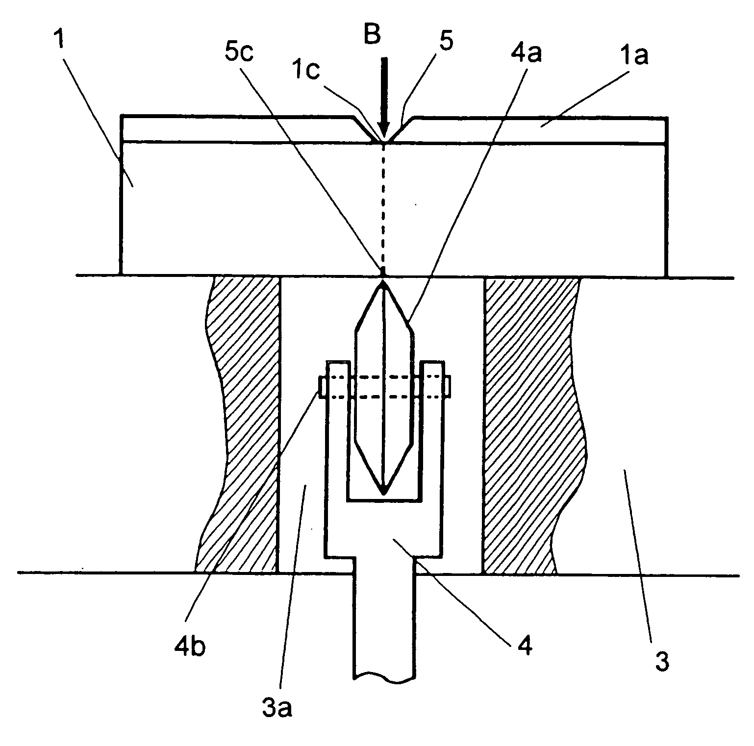
[0093] In the glass substrate cutting step following the scribing step, a pressing force is applied to the surface opposite to that on which the scribed line is formed so that the crack in the scribed line develops until the glass substrate breaks apart. In methods in which scribing is performed on the bottom 1c of the shaved groove 5 formed in the deposited film 1a, in the cutting step following the scribing step, it is necessary to apply a pressing force and cut the glass substrate from below the surface thereof opposite to the scribed surface. Thus, for example, in methods in which the scribed surface, i.e., the film-deposited surface, of the glass substrate is placed directly on the surface plate and a load is applied thereto from above by a press or roller, the pressing force applied to cut apart the glass substrate may destroy or deform the deposited film layer placed directly on the workpiece stage. By contrast, in the cutting method of the seventh embodiment, a pressing forc...

eighth embodiment

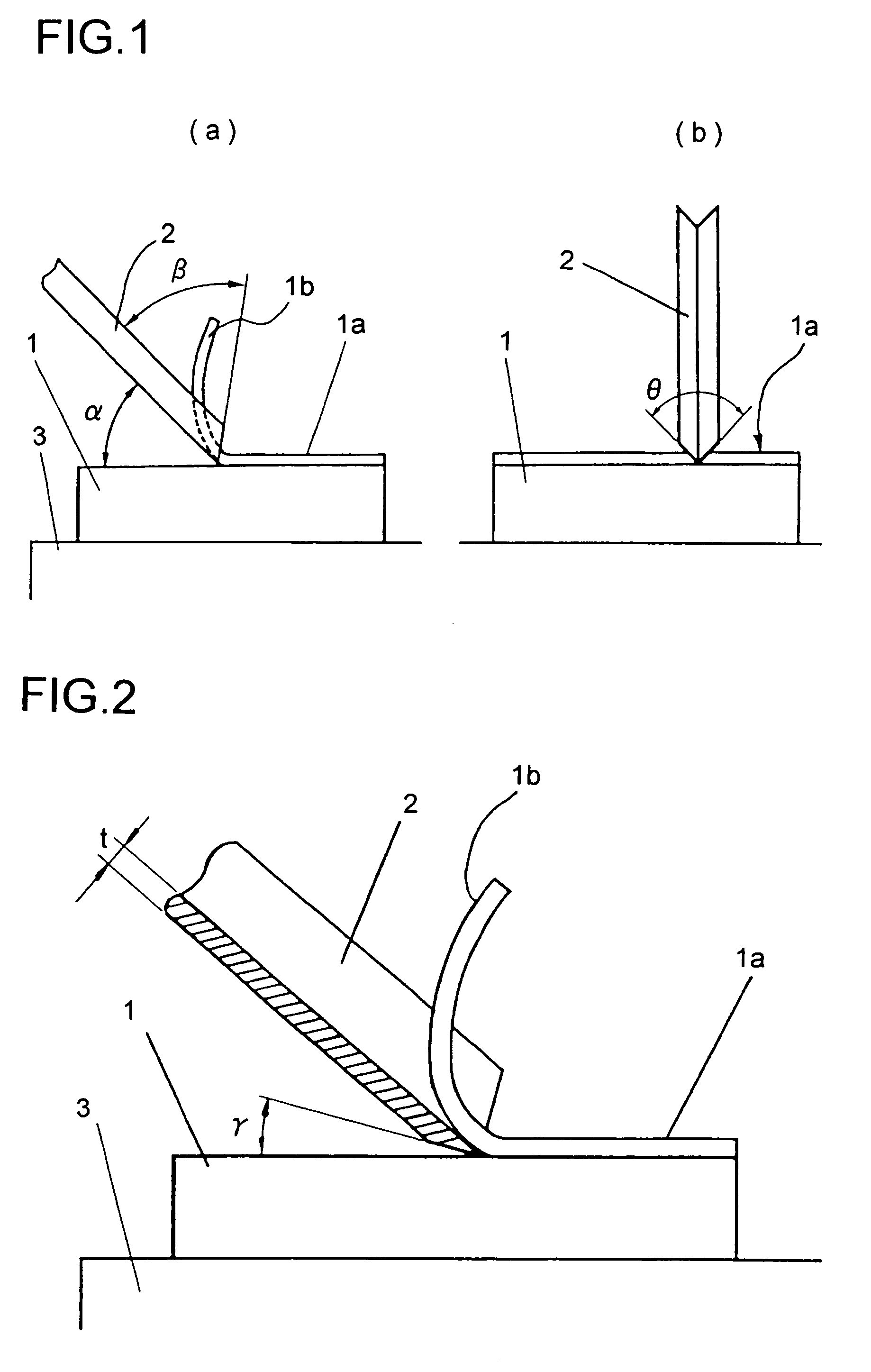
[0096] Next, the workings of the eighth embodiment will be described with the focus placed on what is illustrated in the figures. FIG. 11 shows how a deposited film 1a formed on a glass substrate 1 is shaved and removed by a shaving cutter 62. The angle θ9 at which the shaving cutter is arranged relative to the glass substrate corresponds to the rake angle with which cutting and shaving are performed, and is determined appropriately in the range of from 35° to 45° according to the thickness and material of the deposited film. In this embodiment, when this angle was set equal to 43°, a 1 mm-thick rubber-based deposited film was cut and shaved with satisfactory results. FIG. 11 shows how the shaving cutter 62, while moving in the direction H, cuts and shaves the deposited film 1a. The waste strip 1b shaved off is smoothly ejected along an arc-shaped groove marked as G in FIG. 10. The pressing force with which the shaving cutter 62 is pressed vertically downward against the surface of ...


PUM

PropertyMeasurementUnit
opening angleaaaaaaaaaa
sensing forceaaaaaaaaaa
angleaaaaaaaaaa

Abstract

A method for cutting apart a glass substrate is provided whereby scribing of the glass substrate is possible without being affected by the presence or thickness of a deposited film formed thereon and without scratching the deposited film. To treat a glass substrate (1) having a deposited film (1a), such as a thin film or resin film, formed on one surface thereof, there are provided a shaving means (202), which is a blade that removes strip-shaped portions of the deposited film (1a) to expose strip-shaped regions on the glass substrate (1), and a wheel cutter (14a) that forms scribed lines along the strip-shaped regions exposed on the glass substrate (1). The glass substrate (1) is cut apart along the scribed lines.

Description

TECHNICAL FIELD [0001] The present invention relates to a method and an apparatus for cutting apart a glass substrate, as used as a glass substrate of a liquid crystal display element or the like, that has a deposited-film layer, such as a thin film or film layer, formed on at least one surface thereof. The present invention relates also to a liquid crystal panel composed of a pair of substrate cells bonded together with liquid crystal sealed in between and with polarizer plates bonded to the outer surfaces of the substrate cells, and to an apparatus for fabricating a plurality of such liquid crystal panels by cutting apart a glass substrate that has a plurality of pairs, arranged adjacent to one another, of glass substrate cells bonded together with liquid crystal sealed in between and that has polarizer plates bonded to both surfaces thereof. BACKGROUND ART [0002] Conventionally, a glass substrate is generally cut apart by so-called scribing, specifically by first securing the gla...

Claims


Application Information

Patent Timeline
Patent Type & Authority Applications(United States)
IPC IPC(8): B31B50/25C03B33/033C03B33/07C03B33/10G02F1/1333
CPCB65G2249/04C03B33/033C03B33/07C03B33/074Y10T156/1052C03B33/105G02F1/133351Y10T428/10Y10T156/1064C03B33/10Y10T83/0524Y10T83/0495Y10T83/9372Y10T83/0333Y10T83/04Y10T83/0605C09K2323/00G02F1/13
Inventor YAMABUCHI, KOJIKOMODA, TOMOHISAKAIDA, KAZUYAIZUMI, AKINORIHORIUCHI, TAKANETAKABE, SHINYAFURUYA, TOSHIMITSUKATAYAMA, TETSURO
Owner SHARP KK
Why Eureka
Try Eureka