Electrowetting electrode device with electromagnetic field for actuation of magnetic-bead biochemical detection system

a biochemical detection and electromagnetic field technology, applied in the field of magnetic beads biochemical detection devices, can solve the problems of less precise detection, complicated detection process, and insufficient techniques, and achieve the effect of enhancing magnetic force and reducing dissipation of magnetic lines

Inactive Publication Date: 2005-03-17
NATIONAL TSING HUA UNIVERSITY +1
View PDF7 Cites 143 Cited by
  • Summary
  • Abstract
  • Description
  • Claims
  • Application Information

AI Technical Summary

Benefits of technology

[0045] Preferably, a plurality of magnetic lines of force of the magnetic force is closed by the magnetic layer so as to reduce a dissipation of the magnetic line of force and to enhance the magnetic force.

Problems solved by technology

Separation techniques, such as the physical filtration, crystallization and distillation have been widely applied to separate cells or fragments of cells from aqueous solutions or suspensions However, these techniques have become more and more insufficient as the quantity of the material to be purified becomes smaller and the compactness of the detecting device needs to be realized.
The fluid driver makes the detecting process more complicated and a less precise detection result would be resulted therefrom.
Therefore, such a detecting device 1′ is used only for magnetic-beads detecting and lacks the applicability and the benefit in integration.
Besides, since the detecting device 1′ mentioned above is configured to be operated through the continuous flow, it has a lot of drawbacks, such as a large amount of the reagent is necessary, the samples mixing is insufficient, it is much difficult to drive the fluids, the problem of time-consuming is serious and the detecting result is not precise enough.
However, an integrated function of the magnetic-beads detecting technique with the electrowetting driving technique is not realized nowadays.

Method used


Image

  • Electrowetting electrode device with electromagnetic field for actuation of magnetic-bead biochemical detection system
  • Electrowetting electrode device with electromagnetic field for actuation of magnetic-bead biochemical detection system
  • Electrowetting electrode device with electromagnetic field for actuation of magnetic-bead biochemical detection system

Examples


Embodiment Construction

[0064] The present invention will now be described more specifically with reference to the following embodiments. It is to be noted that the following descriptions of preferred embodiments of this invention are presented herein for purpose of illustration and description only; it is not intended to be exhaustive or to be limited to the precise form disclosed.

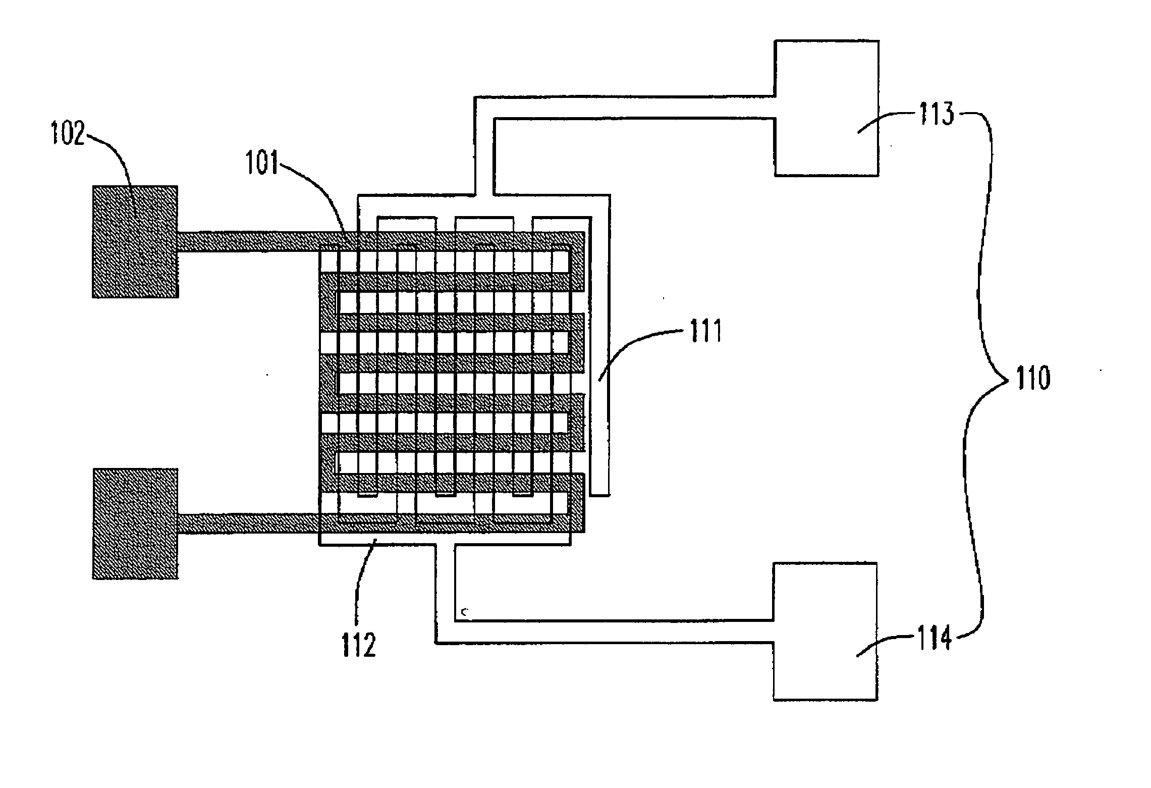
[0065] Please refer to FIGS. 10(a) and 10(b), which respectively illustrate the shapes of the first and the second electrode according to a preferred embodiment of the present invention. A first electrode 101 is designed as zigzag-shaped and has two ends of bonding pods 102, as shown in FIG. 10(a). As shown in FIG. 10(b), a second electrode 110 having a first sub-electrode 111 and a second sub-electrode 112, which are comb-shaped and interlaced with each other, and respectively have ends of binding pods 113 and 114. Accordingly, FIG. 10(c) shows the assembly association of the first electrode 101 and the second electrode 110.

[...


PUM

PropertyMeasurementUnit
hydrophobicaaaaaaaaaa
magneticaaaaaaaaaa
voltageaaaaaaaaaa

Abstract

A detecting device for biochemical detections is provided. The detecting device includes a first substrate, a magnetic layer located on the first substrate, an isolation layer located on the magnetic layer, at least a first electrode located on the isolation layer, a first dielectric layer located on the first electrode, a first hydrophobic layer located on the first dielectric layer, a second substrate, at least a second electrode located on the second substrate and having a cathode and an anode, a second dielectric layer located on the second electrode and a second hydrophobic layer located on the second dielectric layer. The first electrode is zigzag-shaped, and the cathode and the anode of the second electrode are comb-shaped and interlaced with each other.

Description

FIELD OF THE INVENTION [0001] The present invention is related to a magnetic-bead biochemical detecting device, in particular, to a magnetic-bead biochemical detecting device controlled by an electromagnetic field, which is induced by an electrowetting actuated electrode. BACKGROUND OF THE INVENTION [0002] The separation is the critical technique involved in the biochemical detecting. Separation techniques, such as the physical filtration, crystallization and distillation have been widely applied to separate cells or fragments of cells from aqueous solutions or suspensions However, these techniques have become more and more insufficient as the quantity of the material to be purified becomes smaller and the compactness of the detecting device needs to be realized. [0003] The magnetic separation is a well-known technique in the biotechnology, and the magnetic beads have recently been used to help the manipulating and transporting of bio-molecules. It is possible to satisfy the above d...

Claims


Application Information

Patent Timeline
Patent Type & Authority Applications(United States)
IPC IPC(8): B03B7/00B04B5/10F04B17/00G01N33/543
CPCG01N27/745Y10T436/11G01N33/5438
Inventor YUAN, SHIH-JUNYANG, JING-TANGYEH, JER-LIANGYU, CHIH-SHENGHU, YI-CHIUENCHEN, CHIEN-JEN
Owner NATIONAL TSING HUA UNIVERSITY
Why Eureka
Try Eureka