Method and system for high resolution current imaging by direct magnetic field sensing

a technology of direct magnetic field and current imaging, applied in the field of current imaging, can solve the problems of limited thermal and optical techniques commonly used today for fault isolation, ineffective optical and thermal techniques commonly used for fault isolation in the integrated circuit, and the complexity of the package substrate for the new integrated circuit also increases

Inactive Publication Date: 2005-03-17
NEOCERA
View PDF12 Cites 12 Cited by
  • Summary
  • Abstract
  • Description
  • Claims
  • Application Information

AI Technical Summary

Benefits of technology

It is therefore an object of the present invention to provide a tool for non-destructive analysis of buried nanoscale and non-visual defects in semiconductor devices by fiber ba

Problems solved by technology

The increased level of metal interconnect required for the increasing number of transistors, limits thermal and optical techniques commonly used today for fault isolation.
Optical and thermal techniques commonly used for fault isolation in the integrated circuits are ineffective beyond three levels of the metal layerization.
The package substrates for the new integrated circuits are also becoming more complex with finer line dimension approaching 10 nm and many layers of metallization (as high as ten layers), often having several ground and power planes that complicate non-destructive analysis.
Without this capability, the development of new circuits and analysis of failures in semiconductor devices will be greatly hampered, limiting the semiconductor industry in its ability to bring advanced devices quickly to commercialization.
The spatial resolution of the scanning SQUID microscope, however, has historically been limited to lengths greater than several microns, since it is difficult to fabricate functioning SQUIDs with dimensions smaller than the necessary scale.
Magnetic sensors, even in micron scale are generally fabricated on macroscopic substrates, at least hundreds of microns on a side, not allowing these magnetic probes to reach within a few microns of current lines

Method used


Image

  • Method and system for high resolution current imaging by direct magnetic field sensing
  • Method and system for high resolution current imaging by direct magnetic field sensing
  • Method and system for high resolution current imaging by direct magnetic field sensing

Examples


Embodiment Construction

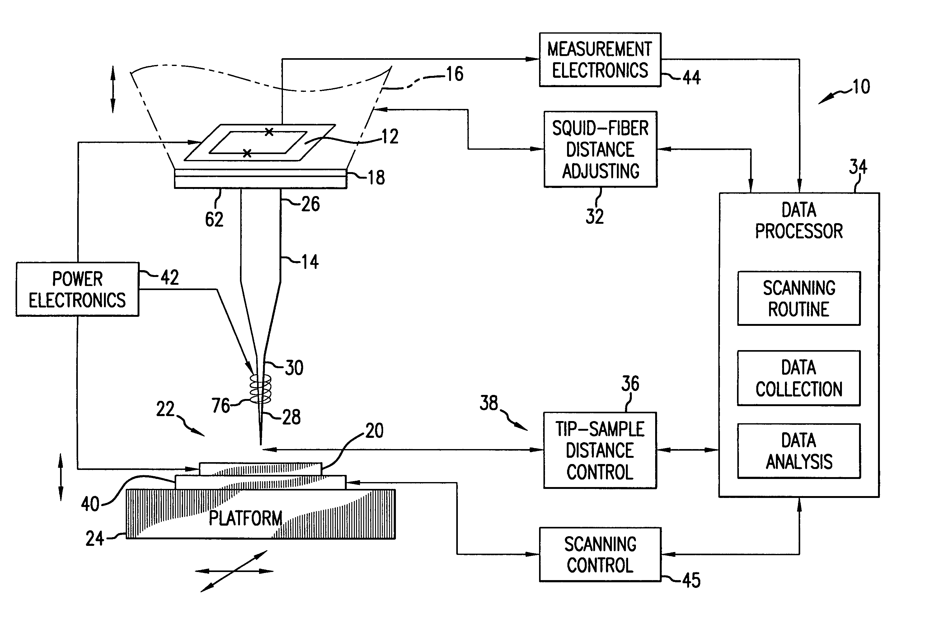
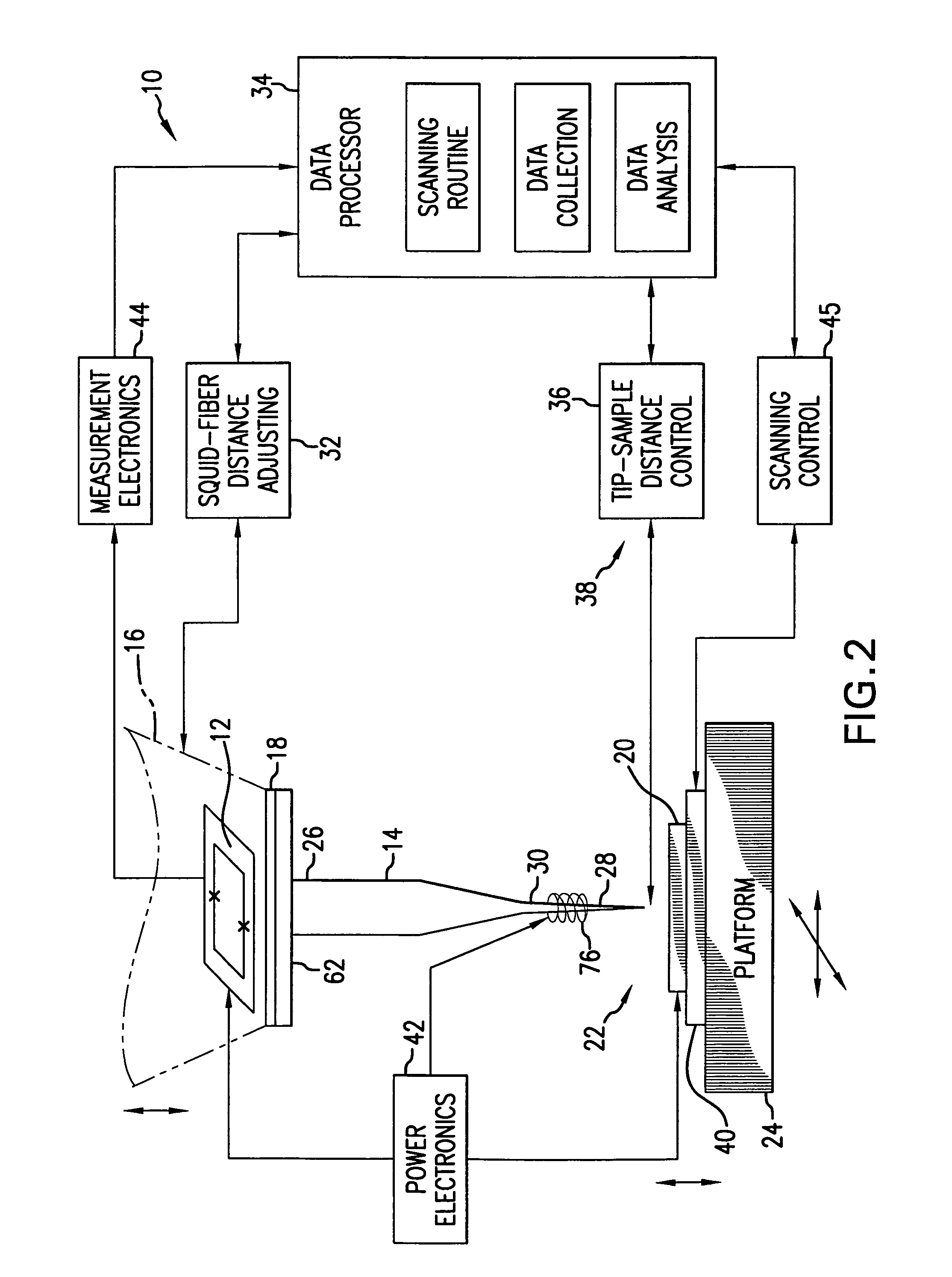
Referring to FIG. 2, the scanning magnetic microscope 10 includes a magnetic sensor 12 and a fiber probe 14 magnetically coupled to each other. The magnetic sensor 12 may be one of a number of commercially available magnetic sensors, however, in the preferred embodiment, the Superconducting Quantum Interference Device (SQUID) has been chosen due to the extraordinary sensitivity of the SQUID to magnetic fields. The SQUID 12 is enveloped in a housing 16 where a vacuum or a cryogenic (liquid nitrogen) atmosphere at 77K is maintained, as is usual for SQUID operation. The housing 16 has a diamond window 18 which provides a thin transparent window of thickness approximating 10 micrometers.

A sample 20 which is the object of the non-destructive study for possible fault presence and location, is positioned in an air (non-vacuum) environment 22 at substantially room temperature. The sample 20 is positioned on a platform 24 which is capable of motion in XYZ direction.

The fiber probe 14 ha...


PUM


Abstract

A scanning microscope for high resolution current imaging by direct magnetic field sensing of a sample maintained in an ambient environment. The scanning microscope uses a magnetic sensor such as a SQUID and a fiber probe magnetically coupled between the SQUID sensor and the sample under study. The fiber probe has a sharply defined tip for high resolution probing and for reaching minute cavities on the surface of the sample. The coupling between the tip of the fiber probe and the sample is controlled by a distance control mechanism, in the range of 1-100 nm. The material of the fiber probe with high permeability and low magnetic noise is chosen to optimize flux transmission to the magnetic sensor. Magnetic coupling to the sensor is maximized by keeping the distance between the end of the fiber probe and the sensor to approximately 0-100 μm. The fiber probe is integrated into the fiber holder for easy replacement of the fiber probe.

Description

FIELD OF THE INVENTION The present invention relates to current imaging; and more particularly to current imaging by direct magnetic field sensing. In overall concept thereof, the present invention relates to magnetic microscopy in which a highly sensitive magnetic sensor, such as for example Superconducting Quantum Interference Device (SQUID) measures magnetic flux emanating from a sample under study which is probed by a fiber probe magnetically coupled to the SQUID. Further, the present invention relates to a magnetic microscope which includes a magnetic sensor, such as a SQUID which is positioned in a vacuum environment having a fiber probe extending between the SQUID and the sample. The sample is positioned in an ambient or air environment at substantially room temperature. The high sensitivity of the SQUID sensor is combined with the high resolution permitted by the use of the fiber probe. The fiber probe has a sharply defined and polished tip on the probing end thereof. Fu...

Claims


Application Information

Patent Timeline
IPC IPC(8): G01R33/038
CPCB82Y25/00B82Y35/00G01Q60/54Y10S505/845G01R33/0385Y10S505/846G01Q70/02
Inventor WOODS, SOLOMON I.KNAUSS, LEE A.LETTSOME, NESCO M.CAWTHORNE, ALFRED B.VENKATESAN, THIRUMALAI
Owner NEOCERA
Why Eureka
Try Eureka