Dual-band antenna having small size and low height

a dual-band antenna, small technology, applied in the direction of resonant antennas, elongated active element feeds, antenna earthings, etc., can solve the problems of obstructing the miniaturization, narrow resonant bandwidth, and inability to secure the desired bandwidth when using the low band, so as to enhance the dramatic gain of electric waves, easy to secure the desired bandwidth, and increase the uniformity of polarized waves

Active Publication Date: 2005-03-17
ALPS ALPINE CO LTD
View PDF5 Cites 29 Cited by
  • Summary
  • Abstract
  • Description
  • Claims
  • Application Information

AI Technical Summary

Benefits of technology

[0017] In such a dual-band antenna, if one divided conductive plate connected to an upper end of the feeding conductive plate is excited, the other divided conductive plate is excited via the third shorting conductive plate which is electromagnetically coupled to the feeding conductive plate. Thus, it is possible to allow the other divided conductive plate to be operated as a radiating element for a parasitic antenna, and also it is possible to set two different resonance points. Further, the difference of resonant frequencies of two resonance points can be increased or decreased by suitably adjusting the degree of the electromagnetic coupling between the feeding conductive plate and the third shorting conductive plate, such that, even when the antenna is miniaturized by reducing an entire size of the fourth radiating conductive plate for the low band, it becomes easy to secure a desired bandwidth by widening a frequency range in which a return loss becomes less than a predetermined value. Further, in the pair of divided conductive plates when exciting, currents having the same magnitude respectively generate to flow in an opposite direction to each other, such that an electric field in one divided conductive plate and an electric field in the other divided conductive plate are cancelled each other. Therefore, while electric waves having a polarized wave direction parallel to the fourth radiating conductive plate are almost never radiated, electric waves having a polarized wave direction orthogonal to the fourth radiating conductive plate are intensively radiated as much, and thus uniformity of polarized waves is raised. Therefore, it is possible to enhance drastically gains to electric waves of specific polarized waves (for example, vertical polarized waves). Moreover, since the fifth radiating conductive plate for the high band operates as a monopole antenna of ¼ wavelength when exciting, a gain of the vertical polarized wave is high, such that it is possible to suppress the height to be low.
[0018] In such a dual-band antenna, the pair of divided conductive plates may be respectively provided with windows which are the approximately same shape. In this case, since the currents which are supplied to the pair of divided conductive plates flow along circumferential edge of the windows, it becomes easy to secure a desired resonant electric field even when the respective divided conductive plates are miniaturized. Therefore, since it is not required for the respective divided conductive plates to form in a meandering shape, radiation efficiency is raised, and an effect or suppressing the narrow band due to the miniaturization is further raised.
[0019] Furth

Problems solved by technology

Recently, although the miniaturization of vehicle dual-band antennas is in high demand, but in the case of miniaturizing the above-mentioned conventional dual-band antenna 1, there is a problem in that a desired bandwidth cannot be secured when using the low band, since antenna devices generally have a feature that a resonant bandwidth is typically narrowed due to the miniaturization.
Here, the bandwidth is a frequency range at which a return loss (the amount of reflection attenuation) is less than −10 dB, and the dual-band antenna must secure a bandwidth wider than an using frequency band with respect to the respective waves of the high band and the low band, which results in obstructing the miniaturization.
Further, in the case in which the radiating conductor for the low band is

Method used


Image

  • Dual-band antenna having small size and low height
  • Dual-band antenna having small size and low height
  • Dual-band antenna having small size and low height

Examples


first embodiment

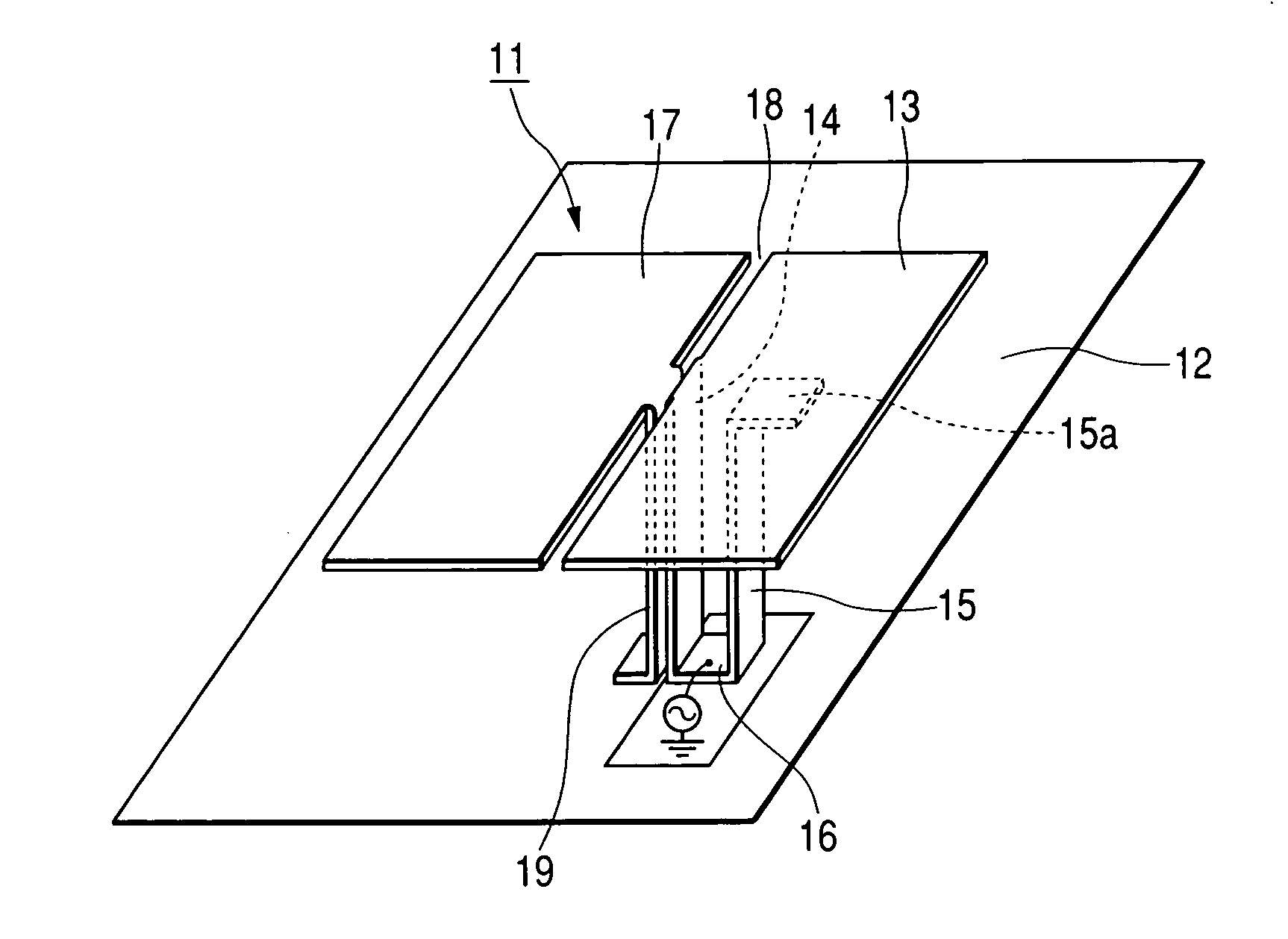
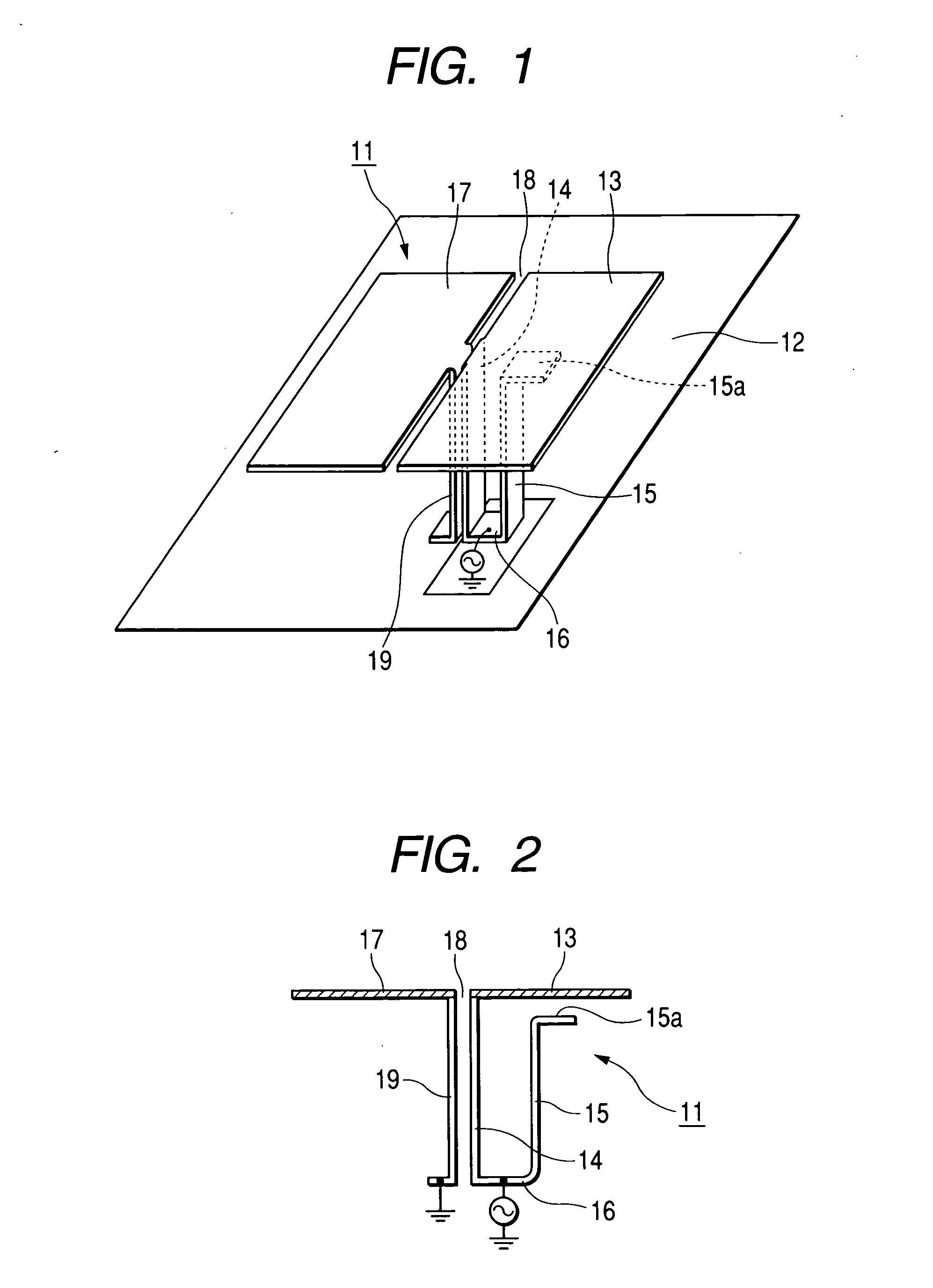
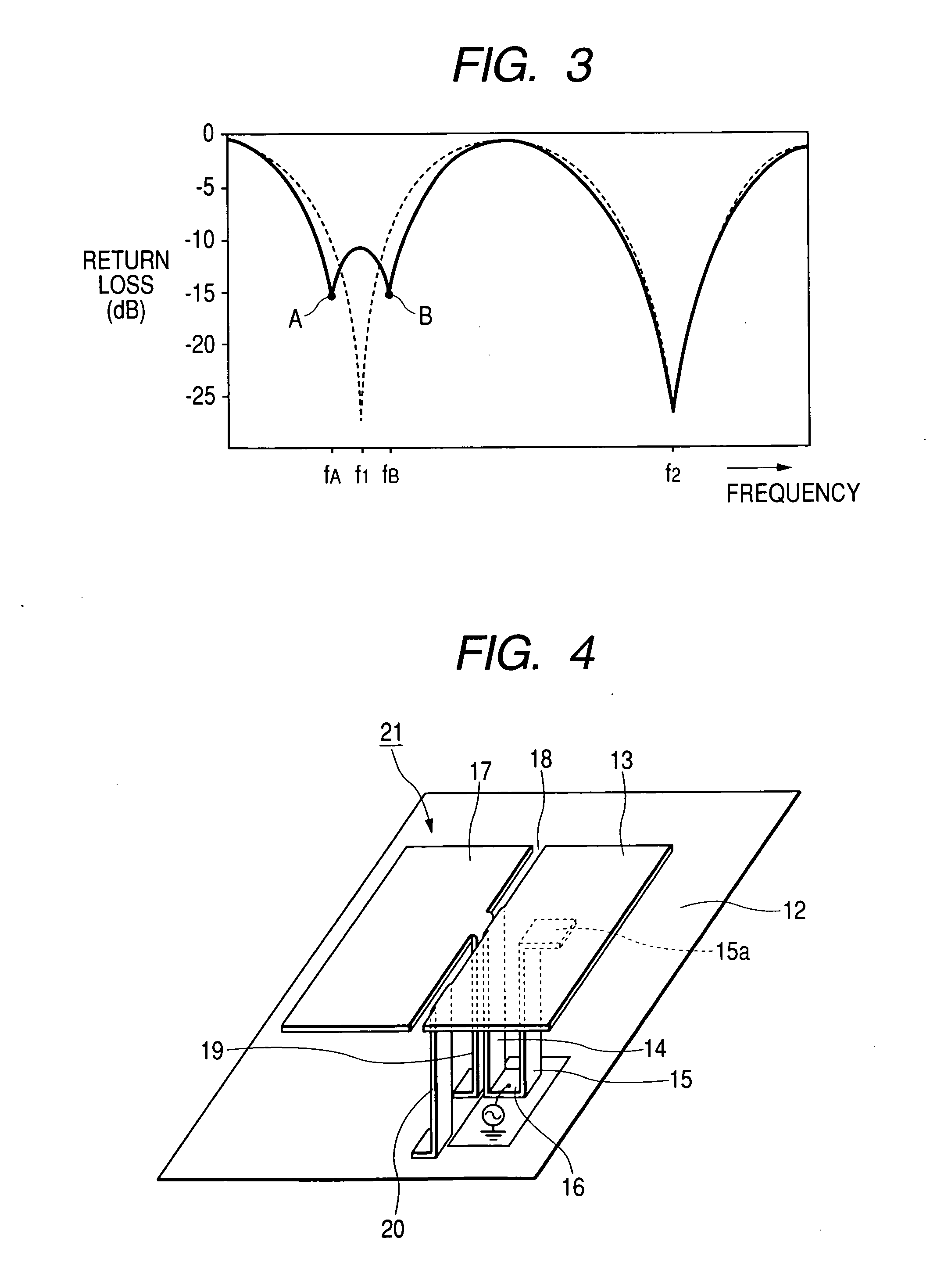
[0033] Embodiments of the present invention will now be described with reference to the drawings. FIG. 1 is a perspective view of a dual-band antenna according to the present invention, FIG. 2 is a partial cross-sectional side view of the dual-band antenna, and FIG. 3 is a characteristic view showing a return loss according to frequencies of the dual-band antenna.

[0034] A dual-band antenna 11 shown in FIGS. 1 and 2 is a metallic plate product by bending a conductive metallic plate such as a copper plate and is fixedly provided on a surface of a grounding conductor 12. The dual-band antenna 11 schematically comprises a first radiating conductive plate 13 arranged to oppose the surface of the grounding conductor 12 in an approximately parallel manner, a feeding conductive plate 14 extending approximately orthogonally from an outer edge of the first radiating conductive plate 13, a second radiating conductive plate 15 stood in approximately parallel to the feeding conductive plate belo...

third embodiment

[0042]FIG. 5 is a perspective view of a dual-band antenna according to the present invention, FIG. 6 is an explanatory view showing respective conductive plates of the dual-band antenna, in which an insulating base member is not shown, FIG. 7 is a plan view of the dual-band antenna, and FIG. 8 is a longitudinal cross-sectional view along the slit of the dual-band antenna, and FIG. 9 is a characteristic view showing a return loss according to frequencies of the dual-band antenna.

[0043] A dual-band antenna 110 shown in FIGS. 5 to 9 is used for a vehicle antenna, and a small-sized antenna in which the transmission and the reception of signal waves of the low band (for example, AMPS band of 800 MHz) and the high band (for example, PCS band of 1.9 GHz) can be selectively performed. The dual-band antenna 110 schematically comprises a supporting substrate 121 with a grounding conductor 120 provided on an entire surface of the rear surface, an angled tube-shaped insulating base member 111 d...


PUM


Abstract

There is provided a dual-band antenna having small size and low height which has a characteristic of not affecting a bandwidth of signal waves of a low band in its miniaturized state. In a dual-band antenna 11, a first radiating conductive plate 13 is arranged to oppose a surface of a grounding conductor 12 in an approximately parallel manner, being excited at a first frequency. A feeding conductive plate 14 extends approximately orthogonally from an outer edge of the first radiating conductive plate 13 and is connected to a feeding circuit A second radiating conductive plate 15 is stood downward the first radiating conductive plate 13, whose lower end is connected to the feeding conductive plate 14. The second radiating conductive plate 15 is excited at a second frequency. A third radiating conductive plate 17 is arranged to oppose the surface of the grounding conductor 12 in an approximately parallel manner on a surface of the grounding conductor and to be adjacent to the first radiating conductive plate 13. A slit 18 is interposed between both radiating conductive plates 13 and 17. A shorting conductive plate 19 extends approximately orthogonally from an outer edge of the third radiating conductive plate 17 and is connected to the surface of the grounding conductor 12. The feeding conductive plate 14 and the shorting conductive plate 19 is arranged close to each other, such that, when a power is supplied, the feeding conductive plate 14 and the shorting conductive plate 19 is electromagnetically coupled.

Description

BACKGROUND OF THE INVENTION [0001] 1. Field of the Invention [0002] The present invention relates to a dual-band antenna having small size and low height which is capable of transmitting and receiving respective signal waves of high and low frequency bands, and which is suitable for using as a vehicle antenna or a portable antenna. [0003] 2. Descriptions of the Related Art [0004] As an antenna having a suitable small size and low height, an inverted F type antenna has been suggested, in which a notch is provided in a radiating conductive plate such that the radiating conductive plate is excited in two types of high and low frequency bands (for example, see Japanese Unexamined Patent Application Publication No. 10-93332, pages 2 to 3, FIG. 1). [0005]FIG. 10 is a perspective view of a conventional inverted F type dual-band antenna. In the inverted F type dual-band antenna 1, a radiating conductive plate 2 is arranged to oppose a surface of a grounding conductor 5 in an approximately p...

Claims


Application Information

Patent Timeline
IPC IPC(8): H01Q5/00H01Q5/378H01Q9/28H01Q9/42
CPCH01Q5/378H01Q9/0421
Inventor YUANZHU, DOU
Owner ALPS ALPINE CO LTD
Why Eureka
Try Eureka