Remote door lock controller for vehicles

a remote door lock and controller technology, applied in the field of vehicle remote door lock controllers, can solve the problems of increasing the number of antennas used on the vehicle rather than reducing the number of, and the number of antennas is large, so as to reduce the number of antennas installed and efficiently detect the portable unit

Inactive Publication Date: 2005-03-17
HONDA MOTOR CO LTD +1
View PDF5 Cites 19 Cited by
  • Summary
  • Abstract
  • Description
  • Claims
  • Application Information

AI Technical Summary

Benefits of technology

[0019] It is an object of the present invention to provide a vehicular remote door lock controller which is capable of efficiently detecting a portable unit that is positioned near a vehicle with a reduced number of antennas installed on the vehicle.

Problems solved by technology

The vehicular remote door lock controller 8 shown in FIGS. 15A and 15B which locks and unlocks the doors without inserting a key into a key cylinder is disadvantageous in that since the antennas 6a through 6e need to be installed in the vicinity of the doors 4a through 4e, respectively, the number of antennas used is large, making the vehicular remote door lock controller 8 costly and heavy.
However, the number of antennas used on the vehicle is increased rather than reduced, and the publication discloses nothing about efforts to reduce the number of antennas used on the vehicle.
However, nothing is disclosed in the publication about efforts to reduce the number of antennas used on the vehicle.

Method used


Image

  • Remote door lock controller for vehicles
  • Remote door lock controller for vehicles
  • Remote door lock controller for vehicles

Examples


1st embodiment

[0086]

[0087] The individual transmission control process for request signals will be described below with reference to the flowchart shown in FIG. 8 and the request signal individual transmission control table 322 shown in FIG. 9B.

[0088] In step S1, the CPU 30 confirms whether there is an input signal from either one of the door sensors 20a, 20b, 20c or not.

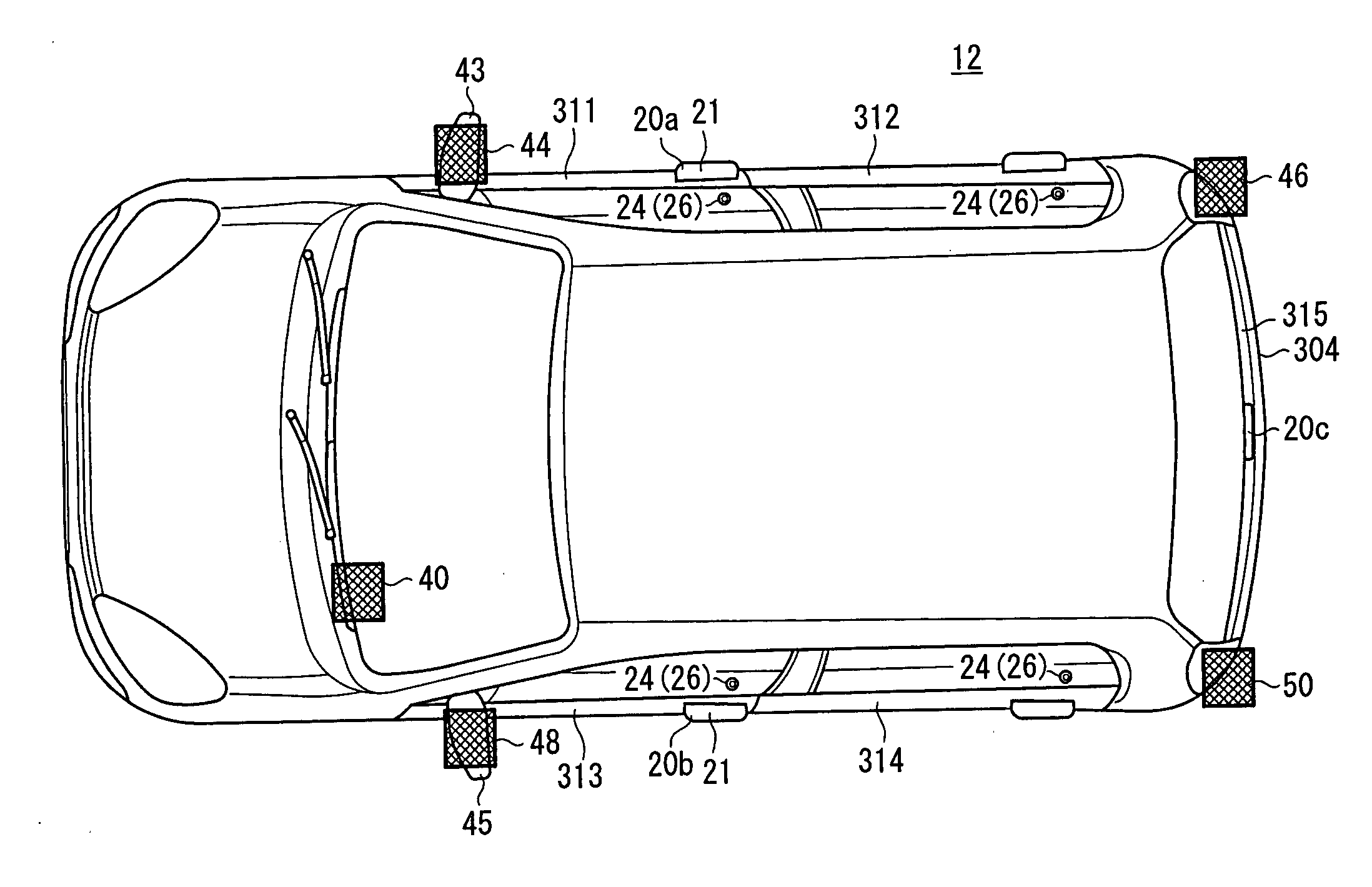
[0089] If it is detected that the door sensor 20a on the outer door handle 21 near the driver seat is activated, i.e., if the owner of the portable unit 18 touches the door handle 21 and an on-signal is supplied from the door sensor 20a, then the CPU 30 refers to the request signal individual transmission control table 322 shown in FIG. 9B, and energizes the LF transmitter 54 to transmit an LF request signal from the LF antenna 44 mounted on the door mirror 43 near the driver seat, in step S2. At this time, the radio wave of the request signal is transmitted only in the effective transmission range TA1 (see FIG. 7) of the LF an...

third and fourth embodiments

[0122] Two embodiments (third and fourth embodiments) of the vehicular remote door lock controller applied to another smart entry system with respect to the simultaneous transmission of request signals will be described below.

[0123] 3rd Embodiment:

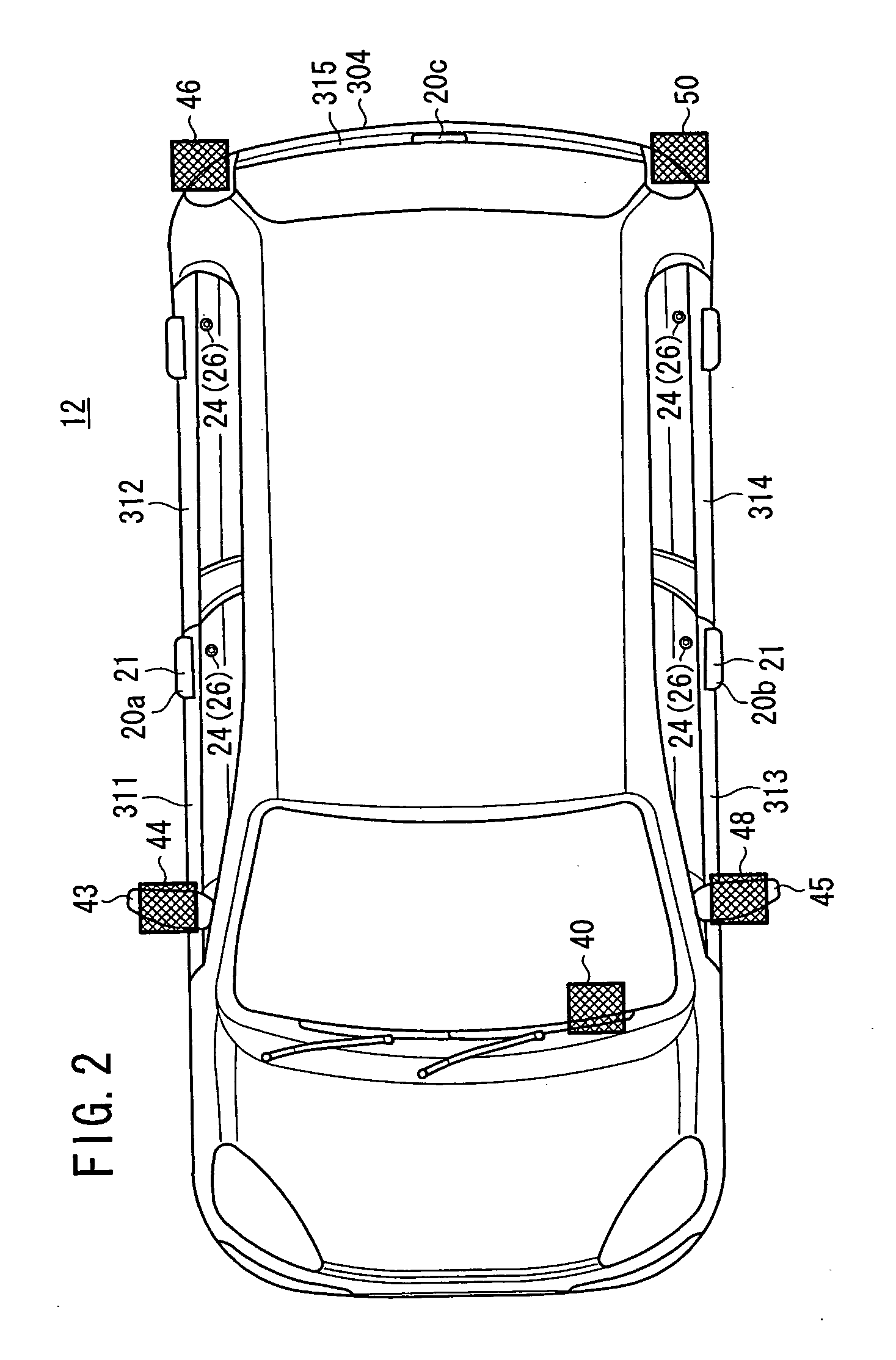
[0124] An intermittent simultaneous transmission control process for intermittently simultaneously transmitting request signals from two LF antennas (44 and 46, 46 and 50, or 48 and 50) including either one of the LF antennas 46, 50 mounted on the corners of the rear bumper 304 will be described below with reference to a flowchart shown in FIG. 12.

[0125] In step S21, the CPU 30 determines whether a condition for intermittently simultaneously transmitting request signals is satisfied or not. Specifically, the condition is satisfied when the CPU 30 confirms that all the door switches 28 are turned off and hence all the doors 311 through 315 are closed. If the condition is satisfied, then the CPU 30 starts an intermittent simultaneous trans...


PUM


Abstract

LF antennas are mounted respectively on the corners of a rear bumper of a vehicle. Radio waves radiated from the LF antennas mounted respectively on the corners of the rear bumper are propagated to the both surfaces of the vehicle on the opposite sides of the corner, providing effective transmission ranges. The remaining LF antennas are mounted respectively on the side surfaces of the vehicle such that their effective transmission ranges overlap the effective transmission ranges of the LF antennas mounted respectively on the corners of the rear bumper.

Description

BACKGROUND OF THE INVENTION [0001] 1. Field of the Invention [0002] The present invention relates to a vehicular remote door lock controller that is suitable for use in a smart entry system for unlocking the doors of a vehicle according to a bidirectional authentication process that is performed with a vehicle-mounted unit (vehicle-side controller) when the owner (user) of a portable unit touches an outer door handle, which functions as a touch sensor, of the vehicle, or a smart entry system for unlocking the doors of a vehicle free of touch sensors according to a bidirectional authentication process between a vehicle-mounted unit (vehicle-side controller) and a portable unit, that automatically starts when the owner of a portable unit approaches the vehicle. [0003] 2. Description of the Related Art [0004] In recent years, there have been proposed various remote door lock controllers for locking and unlocking vehicle doors with a radio signal transmission / reception portable unit wit...

Claims


Application Information

Patent Timeline
Patent Type & Authority Applications(United States)
IPC IPC(8): E05B49/00B60R25/01B60R25/24G07C9/00
CPCB60R25/245E05B81/06E05B81/78E05B81/54G07C2009/00333G07C2009/00793E05B81/16G07C9/00309
Inventor ASAKURA, SUGURUARIE, SHINICHISAWADA, KENICHIYAMANE, KATSUYASUYOSHIMURA, KENTAROOCHI, MASAAKI
Owner HONDA MOTOR CO LTD
Why Eureka
Try Eureka