
Digital broadcasting receiver, driving method, and self-diagnosis method thereof, and self-diagnosis method thereof

a digital broadcasting receiver and driving method technology, applied in the direction of pulse technique, transmission monitoring, dc level restoring means or bias distortion correction, etc., can solve the problems of system stability deterioration system stability fatality, etc., to improve acquisition speed and tracking performance, stable operation, effective utilization

Inactive Publication Date: 2005-03-17
LG ELECTRONICS INC
View PDF6 Cites 56 Cited by
  • Summary
  • Abstract
  • Description
  • Claims
  • Application Information

AI Technical Summary

Benefits of technology

[0022] An object of the present invention is to provide a digital broadcasting receiver, a driving method, and a self-diagnosis method thereof that can perform a stable operation between elements of a system and improve acquisition speed and a tracking performance.
[0023] Another object of the present invention is to provide a digital broadcasting receiver, a driving method, and a self-diagnosis method thereof, which can be effectively utilized in developing a product, by analyzing tracking performance of a receiver using lock information of elements of a system.
[0024] Another object of the present invention is to provide a digital broadcasting receiver, a driving method, and a self-diagnosis method thereof that can swiftly solve problems generated at elements of a system using lock information of the elements of the system.

Problems solved by technology

However, since the multi-medium digital broadcasting receiver is operated in response to an individual lock of each element, there is a problem in that stability of a system is deteriorated if a false lock is generated between the elements.
However, with a gain of a received signal not tracked up to an appropriate level, if a channel equalizer of a blind state is operated, there is high possibility that the channel equalizer operates in its state of local minima.
Such characteristics are fatal to system stability.
Further, since a training sequence does not exist in the QAM method, there is high possibility that a symbol clock recovery and a carrier recovery diverge.
However, the elements at the end should maintain a reset state constantly, but if the channel equalizer operates, there is high possibility that the channel equalizer operates in the state of local minima, which is fatal to system stability.

Method used


Image

  • Digital broadcasting receiver, driving method, and self-diagnosis method thereof, and self-diagnosis method thereof
  • Digital broadcasting receiver, driving method, and self-diagnosis method thereof, and self-diagnosis method thereof
  • Digital broadcasting receiver, driving method, and self-diagnosis method thereof, and self-diagnosis method thereof

Examples


Embodiment Construction

[0044] Reference will now be made in detail to the preferred embodiments of the present invention, examples of which are illustrated in the accompanying drawings.

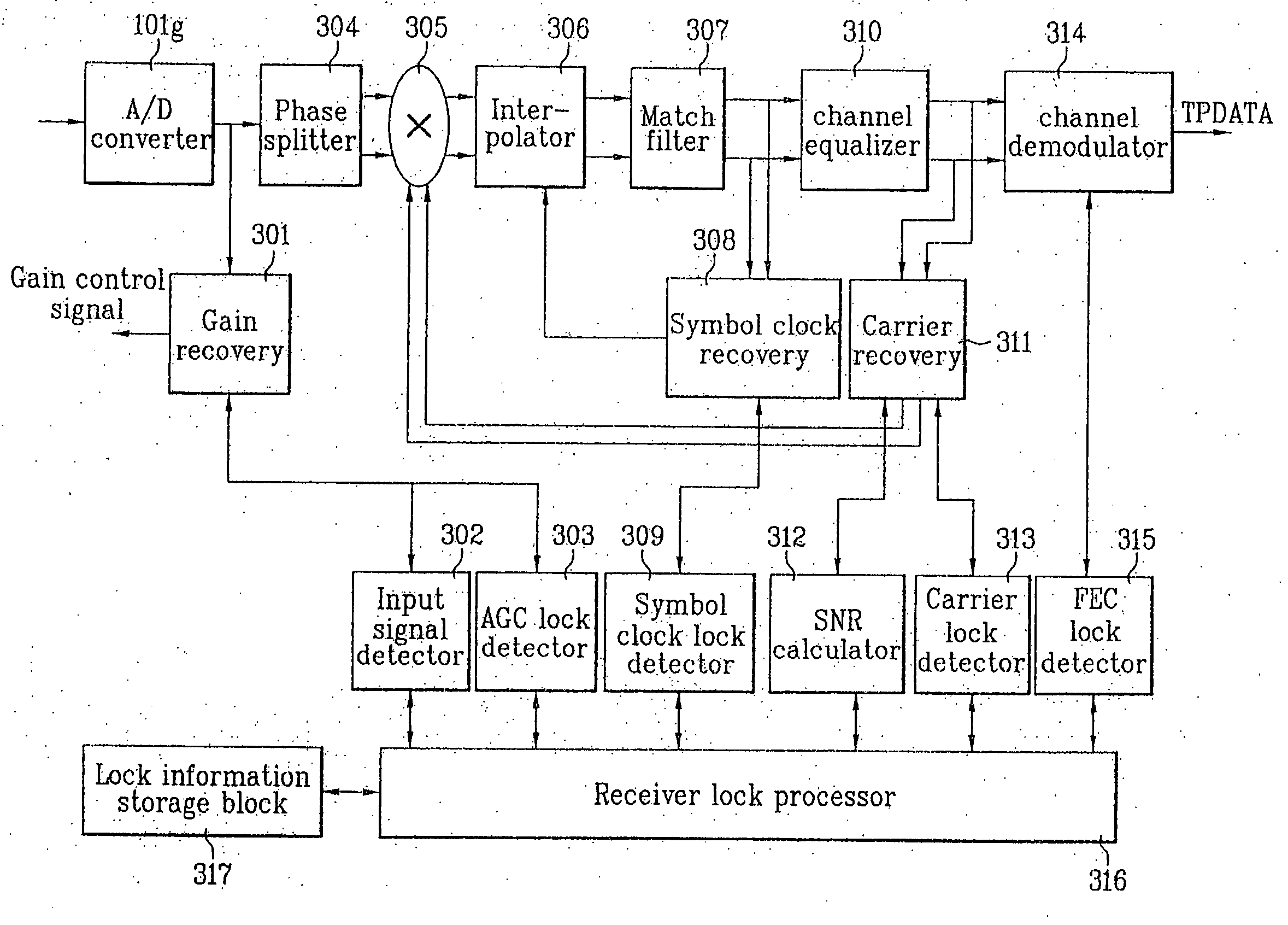
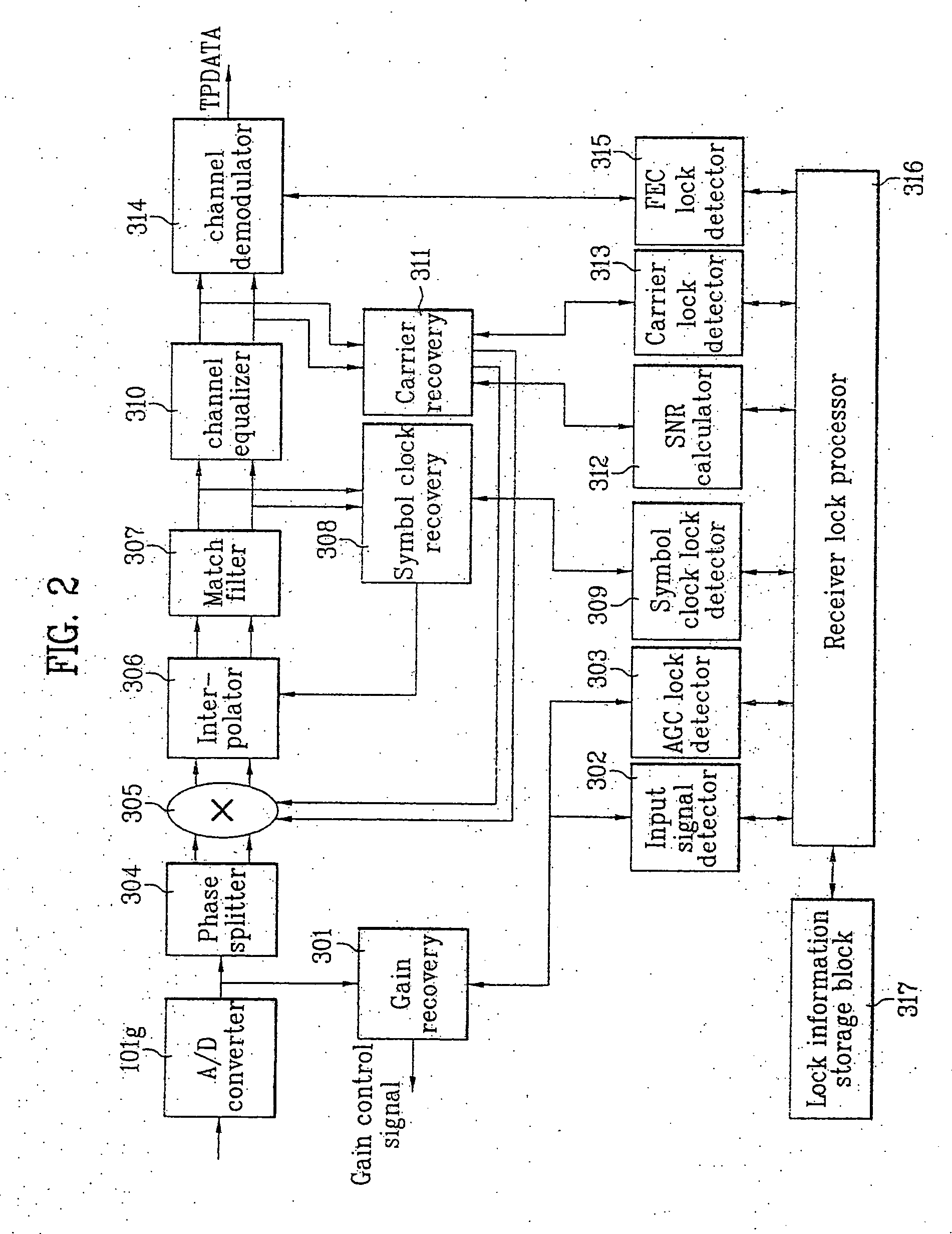
[0045]FIG. 2 is a view illustrating a construction of a digital demodulation block according to the present invention. The digital demodulation block includes: a gain recovery 301; an input signal detector 302; an AGC lock detector 303; a phase splitter 304; a complex multiplier 305; an interpolator 306; a match filter 307; a symbol clock recovery (TR) 308; a symbol clock lock detector 309; a channel equalizer 310; a carrier recovery (CR) 311; a SNR (Signal-to-Noise Ratio) calculator 312; a carrier signal lock detector 313; a channel demodulator 314; a FEC lock detector 315; a receiver lock processor 316; and a lock information storage block 317.

[0046] The gain recovery 301 compensates a size of a signal so that an A / D converter may normally convert an analog signal into a digital signal since an IF signal passing through...


PUM


Abstract

A digital broadcasting receiver, a driving method, and a self-diagnosis method thereof, are provided. The digital broadcasting receiver includes: a digital demodulator for demodulating a digital broadcasting signal; a lock detector for detecting lock signals from the digital demodulator; and a lock processor for controlling the digital demodulator according to the detected lock signal.

Description

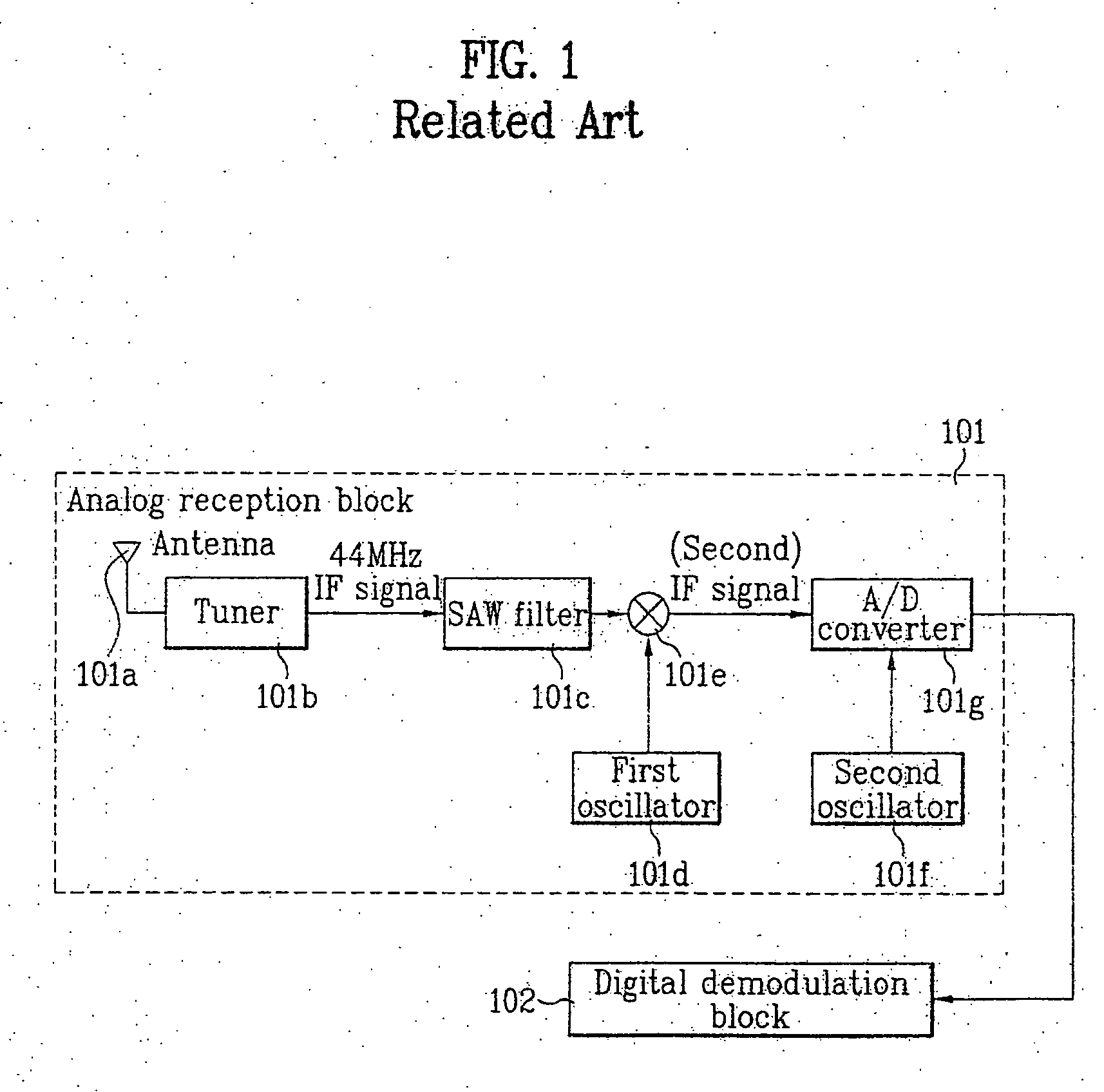
[0001] This application claims the benefit of the Korean Application No. P2003-0064031 filed on Sep. 16, 2003, which is hereby incorporated by reference as if fully set forth herein. BACKGROUND OF THE INVENTION [0002] 1. Field of the Invention [0003] The present invention relates to a digital broadcasting receiver, and more particularly, to a digital broadcasting receiver, a driving method and a self-diagnosis method thereof that can diagnose and settle its problems by itself. [0004] 2. Discussion of the Related Art [0005] In general, a digital broadcasting receiver can be roughly divided into three receiving methods. [0006] First, there is a ground wave broadcasting receiving method, which includes a VSB (Vestigial Side Band) method and an OFDM (Orthogonal Frequency Division Multiplexing) method. Second, a cable broadcasting receiving method, which includes QAM (Quadrature Amplitude Modulation) method. Third, a satellite broadcasting receiving method, which includes QPSK (Quadratur...

Claims


Application Information

Patent Timeline
Patent Type & Authority Applications(United States)
IPC IPC(8): H04H40/18H04N7/015H04L27/26
CPCH04H40/18H04L27/2662H04L27/2657H04N7/015
Inventor LEE, TAE WON
Owner LG ELECTRONICS INC
Learn More