Frequency generator and communication system using the same

a frequency generator and frequency technology, applied in the field of frequency generators and communication systems, can solve the problems of inability to correct alternating-current delay, oscillation frequency fluctuation due to temperature variation, etc., and achieve the effect of high-stable oscillation frequency

Inactive Publication Date: 2005-03-17
RENESAS TECH CORP
View PDF7 Cites 36 Cited by
  • Summary
  • Abstract
  • Description
  • Claims
  • Application Information

AI Technical Summary

Benefits of technology

[0022] Accordingly, an object of the present invention is to provide a frequency generator and a communication system using the same which can g

Problems solved by technology

Oscillation frequency fluctuation due to temperature variatio

Method used


Image

  • Frequency generator and communication system using the same
  • Frequency generator and communication system using the same
  • Frequency generator and communication system using the same

Examples


embodiment 1

[0064] [Embodiment 1]

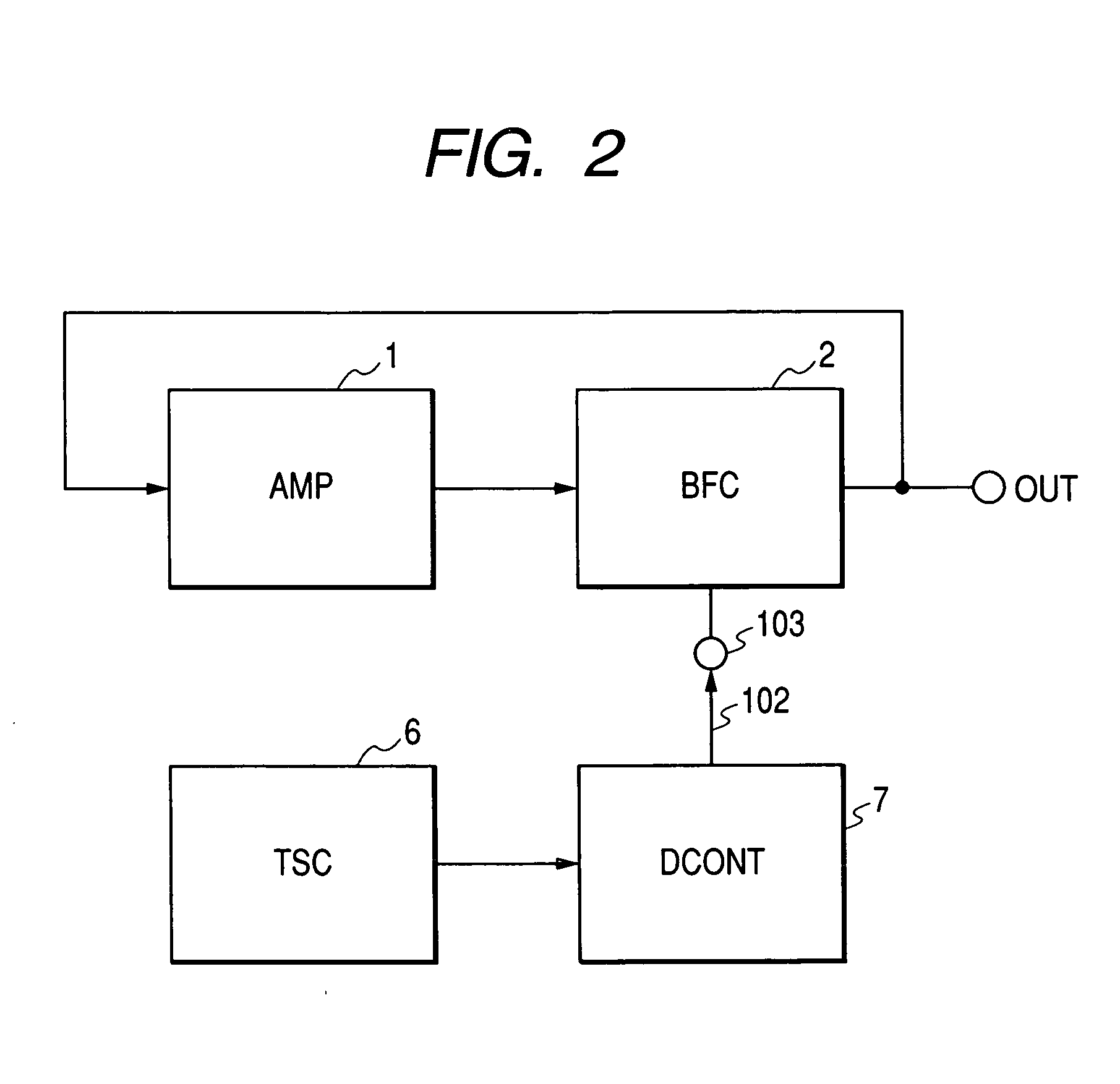
[0065]FIG. 3 is a block diagram showing a first embodiment of a frequency generator according to the present invention. The frequency generator of this embodiment has an amplifier 1, a buffer circuit (BFC) 2 feeding back an output of the amplifier 1 to its input, a reference voltage generator (REFV) 4, and a temperature coefficient converter (TCC) 5. In this embodiment, the temperature stabilizing circuit 6 of FIG. 2 is replaced with the reference voltage generator 4 outputting a voltage stable to temperature and having predetermined dependence, and the delay-time control circuit (DCONT) 7 is replaced with the temperature coefficient converter 5 converting the temperature dependence of an output voltage of the reference voltage generator 4 to predetermined temperature dependence. The same reference numerals in the following description indicate identical or similar construction parts.

[0066]FIG. 4 shows a block diagram of the frequency generator showing a constr...

embodiment 2

[0071] [Embodiment 2]

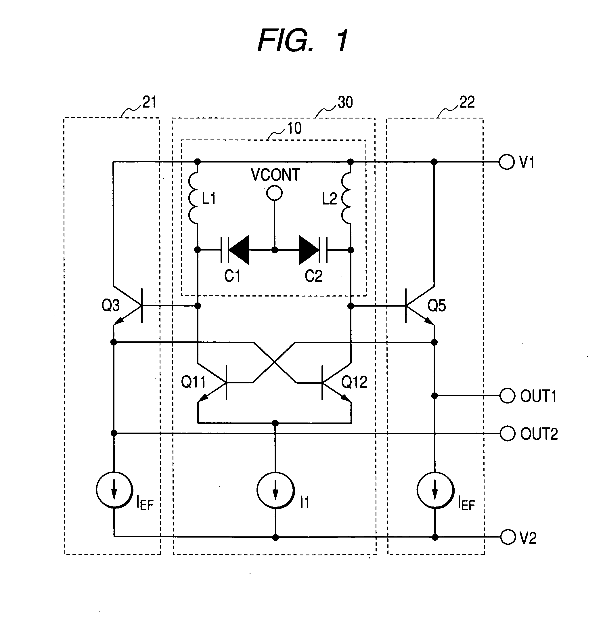
[0072]FIG. 6 is a circuit block diagram showing a second embodiment of a frequency generator according to the present invention. The frequency generator of this embodiment has a differential amplifier 1 having an LC resonance circuit 10 as a load, buffer circuits 21, 22 constructed by an emitter follower circuit feeding back each output of the differential amplifier 1 to each input, a reference voltage generator 4, and a temperature coefficient converter 5.

[0073] The resonance circuit 10 is a circuit in which inductors L1, L2 and variable capacitors C1, C2 such as variable capacitor diodes are connected in parallel. The differential amplifier 1 has a differential transistor pair Q11, Q12 of bipolar transistors and constant-current source I1.

[0074] A frequency control voltage is applied to frequency control terminal VCONT of the variable capacitors C1, C2 to control an oscillation frequency. The differential amplifier 1 amplifies signals inputted from the bases...

embodiment 3

[0089] [Embodiment 3]

[0090]FIG. 9 is a diagram showing a third embodiment of a frequency generator according to the present invention and is another construction example of the temperature coefficient converter 5 used in the frequency generator of the differential amplifier construction shown in FIG. 6. It is a circuit which can improve the noise characteristic of the temperature coefficient converter of FIG. 8 and obtain temperature dependence in a wide range.

[0091] The temperature coefficient converter of this embodiment has a collector output stage 51 receiving as an input an output 101 of the reference voltage generator, having NPN bipolar transistor Q10 and resistances R91, R92 and fetching an output from the collector of the transistor Q10, an emitter output stage 52 receiving as an input an output of the collector output stage 51, a collector output stage 53 receiving as an input an output of the emitter output stage 52, having NPN bipolar transistor Q30 and resistances R93,...


PUM


Abstract

A frequency generator which can perform stable frequency oscillation unaffected by temperature variation.
A frequency generator having a differential amplifier (1) having an LC resonance circuit (10) as a load and buffer circuits (21, 22) feeding back an output of the differential amplifier to its input, wherein a temperature coefficient converter (5) converting an output voltage of a reference voltage generator (4) and its temperature dependence to a voltage having a predetermined voltage and temperature coefficient and outputting it is provided to control bias currents IEF of emitter follower circuits to be in proportion to temperature variation. There are a characteristic in which delay time of the emitter follower circuits constructing the buffer circuits is in inverse proportion to a transconductance of transistors and a characteristic in which the transconductance is in inverse proportion to temperature and is in proportion to the bias currents IEF. An oscillation frequency stable to temperature variation can be obtained.

Description

CLAIM OF PRIORITY [0001] The present application claims priority from Japanese patent application serial no. JP 2004-187412 filed on Jun. 25, 2004, which further claims priority from Japanese patent application serial no. JP 2003-305009 filed on Aug. 28, 2003, the contents of which are hereby incorporated by reference into this application. BACKGROUND OF THE INVENTION [0002] 1. Field of the Invention [0003] The present invention relates to a frequency generator and a communication system using the same. More specifically, the present invention relates to temperature compensation of an oscillation frequency of a frequency generator. [0004] 2. Description of the Related Art [0005]FIG. 1 is a circuit diagram showing an example of a differential LC resonance type of voltage controlled frequency generator using a prior art LC resonator. The differential LC resonance type of voltage controlled frequency generator has a differential amplifier 30 having an LC resonator 10 as a load and feed...

Claims


Application Information

Patent Timeline
IPC IPC(8): H03B5/12H03F1/30H03F3/343H03F3/345H03B5/04H03F3/45H03F3/50H04B1/26
CPCH03F1/30H03F3/3435H03F3/345H03F3/4508H03F3/50H03B5/1221H03F2203/45264H03B5/1228H03B5/1231H03B5/1215H03B5/1243H03F2200/372
Inventor NAKAMURA, TAKAHIROOHHATA, KENICHIMASUDA, TORU
Owner RENESAS TECH CORP
Why Eureka
Try Eureka