Method for producing magnetostrictive element and sintering method

a magnetostrictive element and sintering technology, applied in the field of method for producing magnetostrictive elements, can solve the problems of reducing yield and deteriorating strength, and achieve the effect of improving element yield

Inactive Publication Date: 2005-03-24
TDK CORPARATION
View PDF2 Cites 38 Cited by
  • Summary
  • Abstract
  • Description
  • Claims
  • Application Information

AI Technical Summary

Benefits of technology

[0011] The present invention is developed to solve these problems involved in the conventional techniques. It is an object of the present invention to provide a method for producing a magnetostrictive element and a sintering method which can prevent formation of the nests and thereby improve element yield.
[0018] The hydride present in the compact is thermally decomposed at around 650° C. to release hydrogen gas. Therefore, release of hydrogen gas may not be accelerated when the first temperature, as the upper limit to keep atmosphere pressure at a given level or less, is below 450° C. At above 750° C., on the other hand, the density of the sintered body may be decreased.
[0019] The atmosphere to be supplied after temperature reaches the first level is preferably of a non-oxidative gas, e.g., inert gas. Supplying a hydrogen gas or a mixture of hydrogen gas and inert gas is also effective to improve density of the finally obtained sintered body. When hydrogen gas and inert gas are supplied together, it is preferable to mix them at 650° C. or higher during the heating step, to avoid oxidation by oxygen remaining in a very small quantity.
[0022] Keeping the first temperature at a level at which thermal decomposition of the hydride starts or higher is effective for reducing a generation rate of the nests in the sintered body.

Problems solved by technology

However, the conventional techniques involve the following problems.
As a result, the magnetostrictive element thus produced has nests formed by the gasified hydrogen bubbles, which deteriorate strength and magnetic properties of the magnetostrictive element, and also reduce yield.

Method used


Image

  • Method for producing magnetostrictive element and sintering method
  • Method for producing magnetostrictive element and sintering method
  • Method for producing magnetostrictive element and sintering method

Examples


example 1

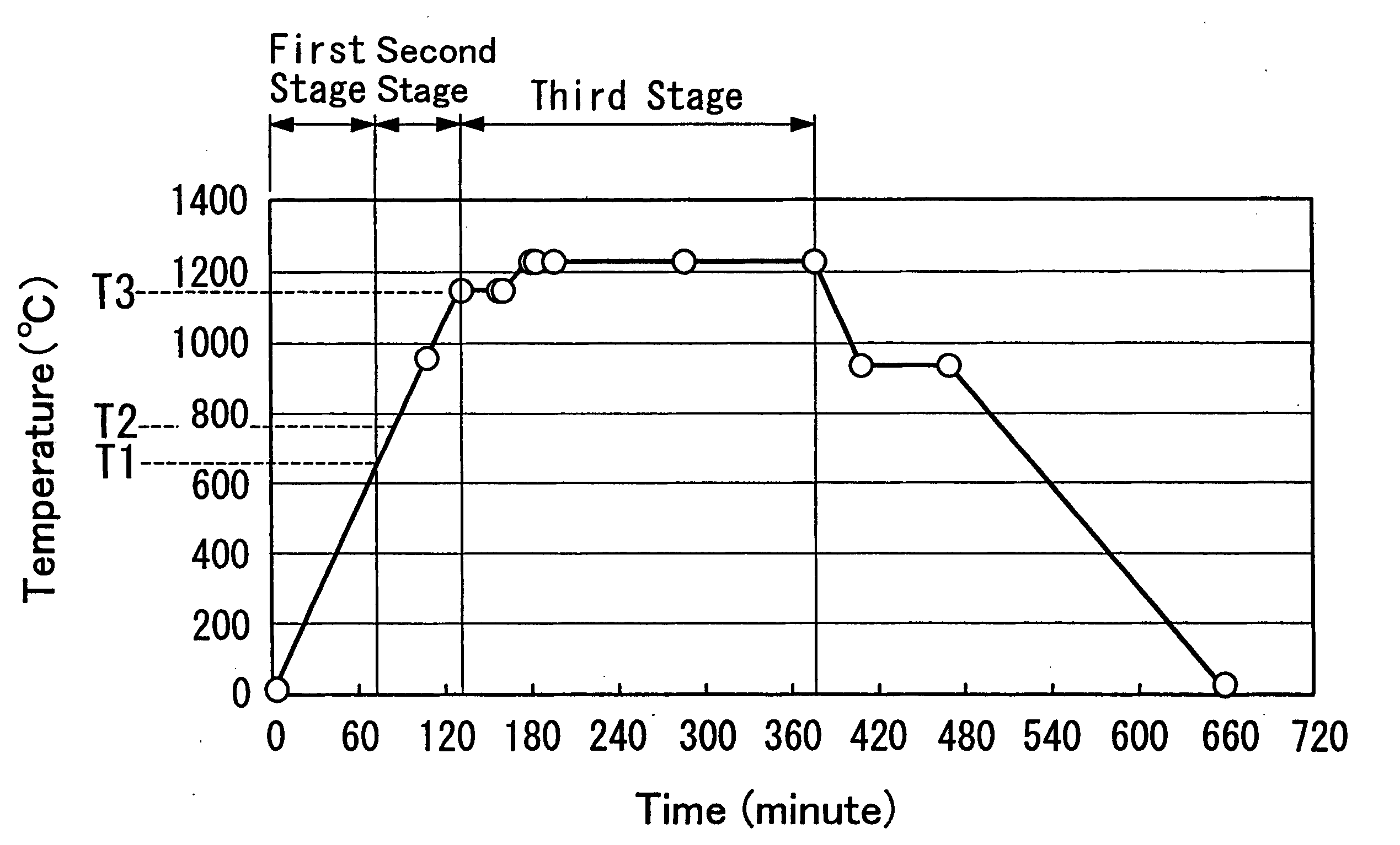
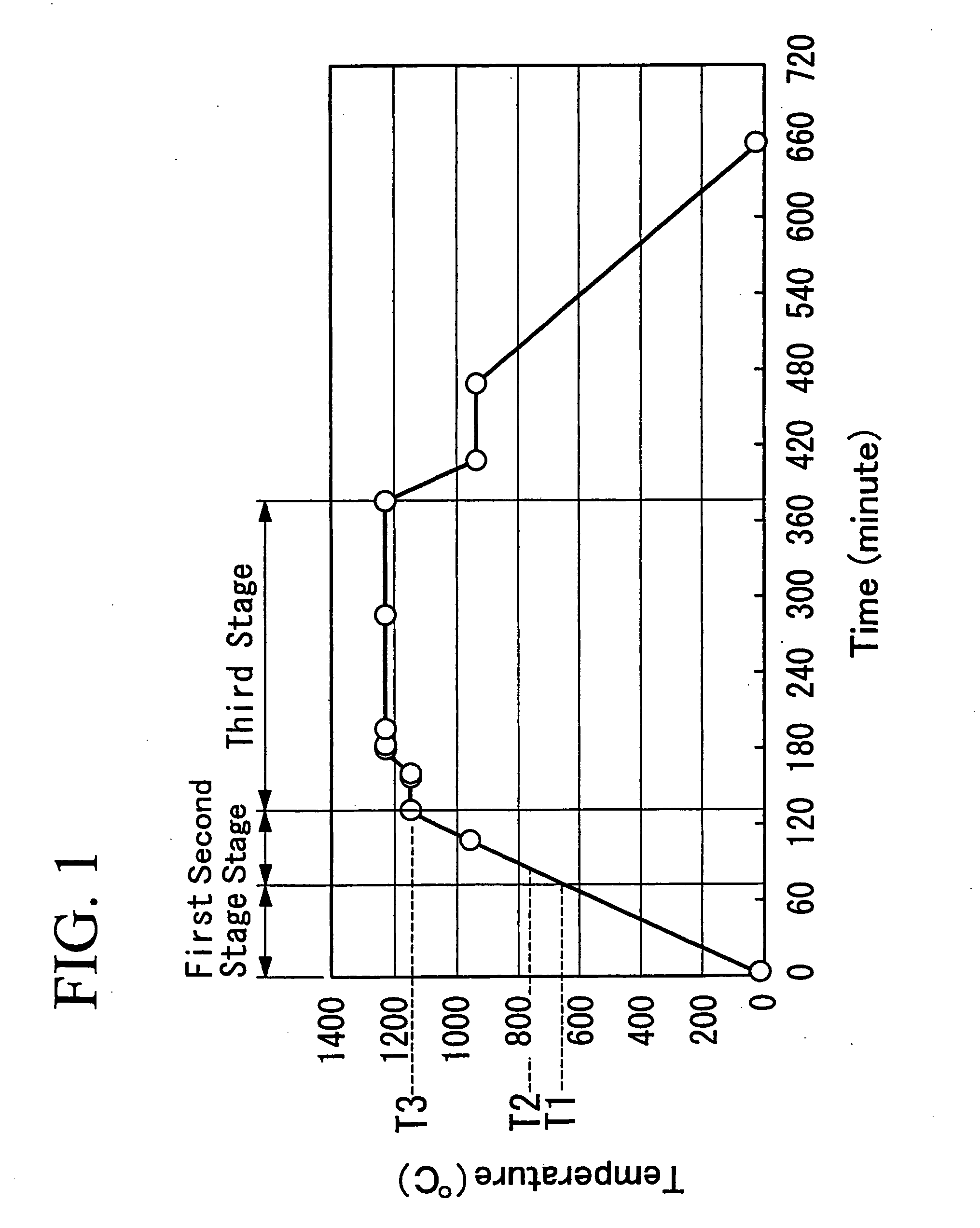
[0065] Hydrogen generation rate during the first stage (heating stage) was measured under different conditions in the furnace, under almost vacuum and in an inert gas (Ar gas) atmosphere, to compare the effects of these conditions. The results are described below.

[0066] As for Starting Material A, Tb, Dy and Fe were weighed and then melted in an inert gas atmosphere of Ar to prepare the alloy having a composition Tb0.4Dy0.6Fe1.94. It was annealed to secure an even concentration distribution of each metal element of the prepared alloy and remove a dissimilar phase when it deposits, and was then milled by an atomizer. Next, as for Starting Material B, DyH2 and Fe were weighed at given ratio and were melted in an inert gas atmosphere of Ar, where the DyH2 / Fe ratio was set in such a way that Starting Material B had a composition of Dy2.0Fe after hydrogen was released during the sintering step. The resulting alloy having a composition of Dy2.0Fe was also milled in a similar manner by an...

example 2

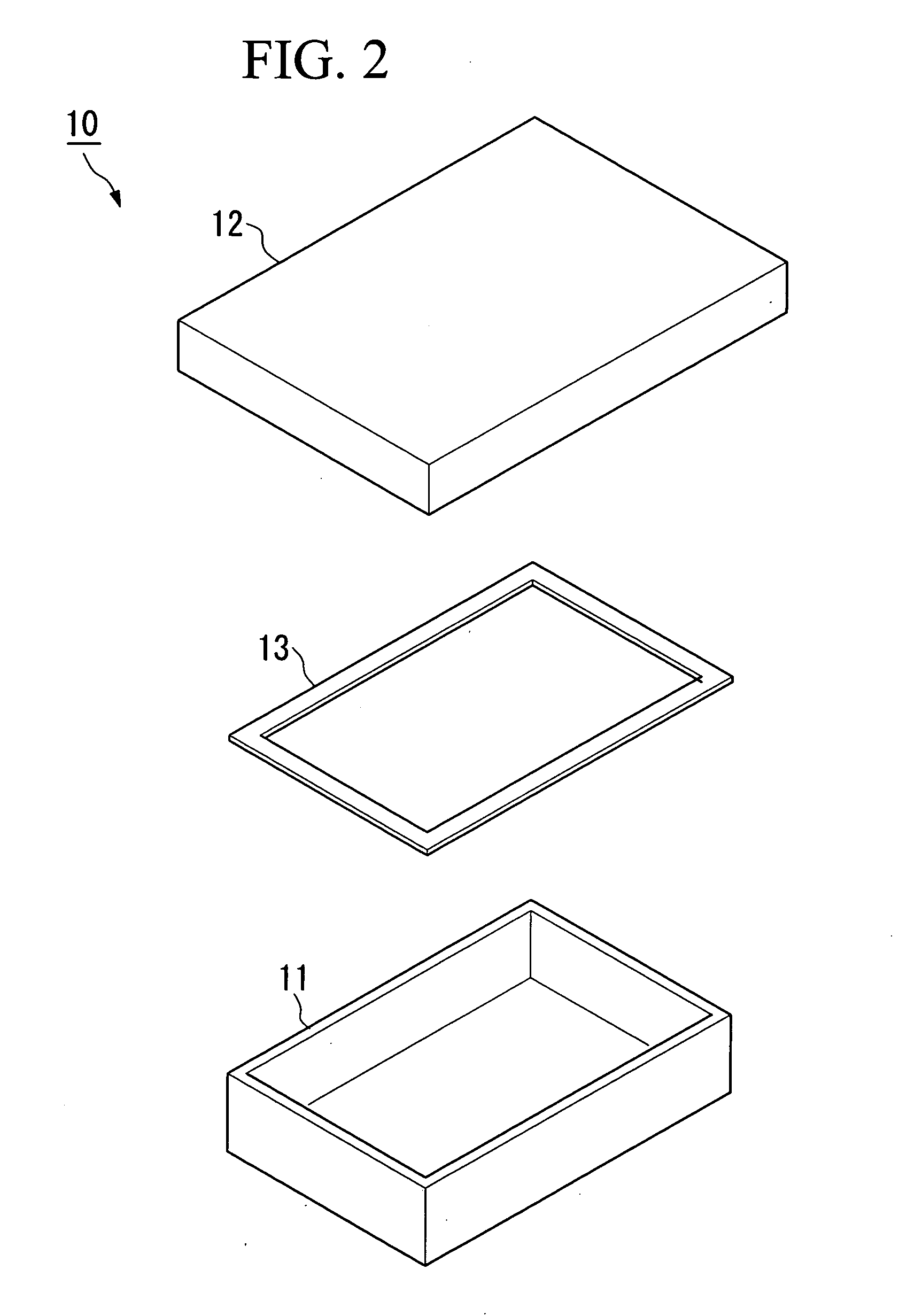
[0073] Formation of nests in the magnetostrictive element sintered while it was held in the above-mentioned sintering container 10 was investigated. The results are described below.

[0074] First, 773 g of Starting Material A, Tb0.4Dy0.6Fe1.94, 101 g of Starting Material B described below and 46 g of Starting Material C, Fe, were milled and mixed with each other to prepare the starting alloy powder having a composition of Tb0.3Dy0.7Fe1.88. It was compacted in a mold in a magnetic field of 8 kOe, to prepare the compact 100. It had a stick shape, 7 mm in diameter and 100 mm in length. The DyH2 / Fe ratio was set for Starting Material B to have a composition of Dy2.0Fe after hydrogen was released, as in EXAMPLE 1.

[0075] The compact 100, put in the sintering container 10, was heated in a furnace following the temperature profile shown in FIG. 1.

[0076] The container body 11 of the sintering container 10 had internal dimensions of 170 mm in width, 240 mm in length and 60 mm in height.

[007...


PUM

PropertyMeasurementUnit
temperatureaaaaaaaaaa

Abstract

In the step of sintering a compact that is finally to be a magnetostrictive element, when the temperature in a furnace is elevated, the atmosphere in the furnace is evacuated by a vacuum pump to keep the pressure in the furnace at negative pressure in a temperature range that allows thermal decomposition of hydride present in the compact to release hydrogen gas to accelerate release of hydrogen from the compact.

Description

BACKGROUND OF THE INVENTION [0001] 1. Field of the Invention [0002] The present invention relates to a method for producing a magnetostrictive element, and a method for sintering an object to be sintered containing a hydride. [0003] 2. Description of the Related Art [0004] Magnetostrictive elements have been used for various devices, e.g., linear actuators, vibrators, pressure torque sensors, vibration sensors and gyro sensors. [0005] When a magnetostrictive element is used for a linear actuator, vibrator or the like, a driving force is generated by changing a magnetic field applied to change the dimensions of the magnetostrictive element. When a magnetostrictive element is used for a pressure torque sensor, vibration sensor, gyro sensor or the like, on the other hand, it detects its permeability changing with dimensional changes of the magnetostrictive element caused by external pressure and thereby sensing is conducted. [0006] These magnetostrictive elements are produced by compac...

Claims


Application Information

Patent Timeline
Patent Type & Authority Applications(United States)
IPC IPC(8): B22F3/00B22F3/10H01F1/055H01F41/02H01L41/22
CPCB22F3/001B22F3/101B22F2998/00B22F2999/00H01F1/0557H01F41/0273H01L41/20H01L41/47C22C1/0441B22F3/02B22F2202/05B22F2201/20B22F2201/013H10N35/85H10N35/01
Inventor TOKORO, SEIGOTOMIZAWA, SHIROMORI, TERUO
Owner TDK CORPARATION
Why Eureka
Try Eureka