AC-driven electroluminescent element having light emission layer in which particles each containing fluorescent portion are densely arranged

Inactive Publication Date: 2005-03-24
FUJIFILM CORP +1
View PDF9 Cites 19 Cited by
  • Summary
  • Abstract
  • Description
  • Claims
  • Application Information

AI Technical Summary

Benefits of technology

[0042] (V) In order to accomplish the aforementioned second object, the fifth aspect of the present invention is provided. According to the fifth aspect of the present invention, there is provided a method for producing an AC-driven electroluminescent element including a pair of electrodes, a light emission layer located between the pair of electrodes, and at least one insulation layer which is arranged on at least one side of the light emission layer. The method comprises the steps of: (a) forming a layer of a material in which a group of particles are dispersed in a pyrolytic binder; (b) thermally decomposing the pyrolytic binder in the layer formed in step (a) and removing the pyrolytic binder from the layer formed in step (a); and (c) impregnating the layer from which the pyrolytic binder is removed in step (b), with a filler material, so as to form the light emission layer. The group of particles is a first, second, third, or fourth group of particles, or a combination of two or more groups of the first, second, third, and fourth groups of particles, w

Problems solved by technology

However, the intensities of electroluminescent light emitted from the dispersion type electroluminescent elements are lower than the intensities of electroluminescent light emitted from the thin-film type electroluminescent elements, the variety of colors of the light emitted from the dispersion type electroluminescent elements is small, and the dispersion type electroluminescent elements are not suitable for use

Method used


Image

  • AC-driven electroluminescent element having light emission layer in which particles each containing fluorescent portion are densely arranged
  • AC-driven electroluminescent element having light emission layer in which particles each containing fluorescent portion are densely arranged
  • AC-driven electroluminescent element having light emission layer in which particles each containing fluorescent portion are densely arranged

Examples


first embodiment

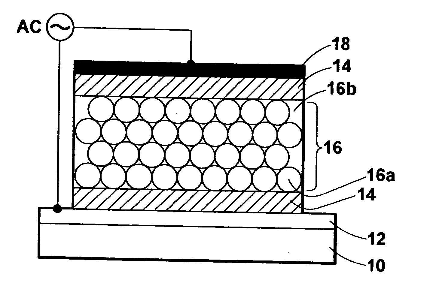
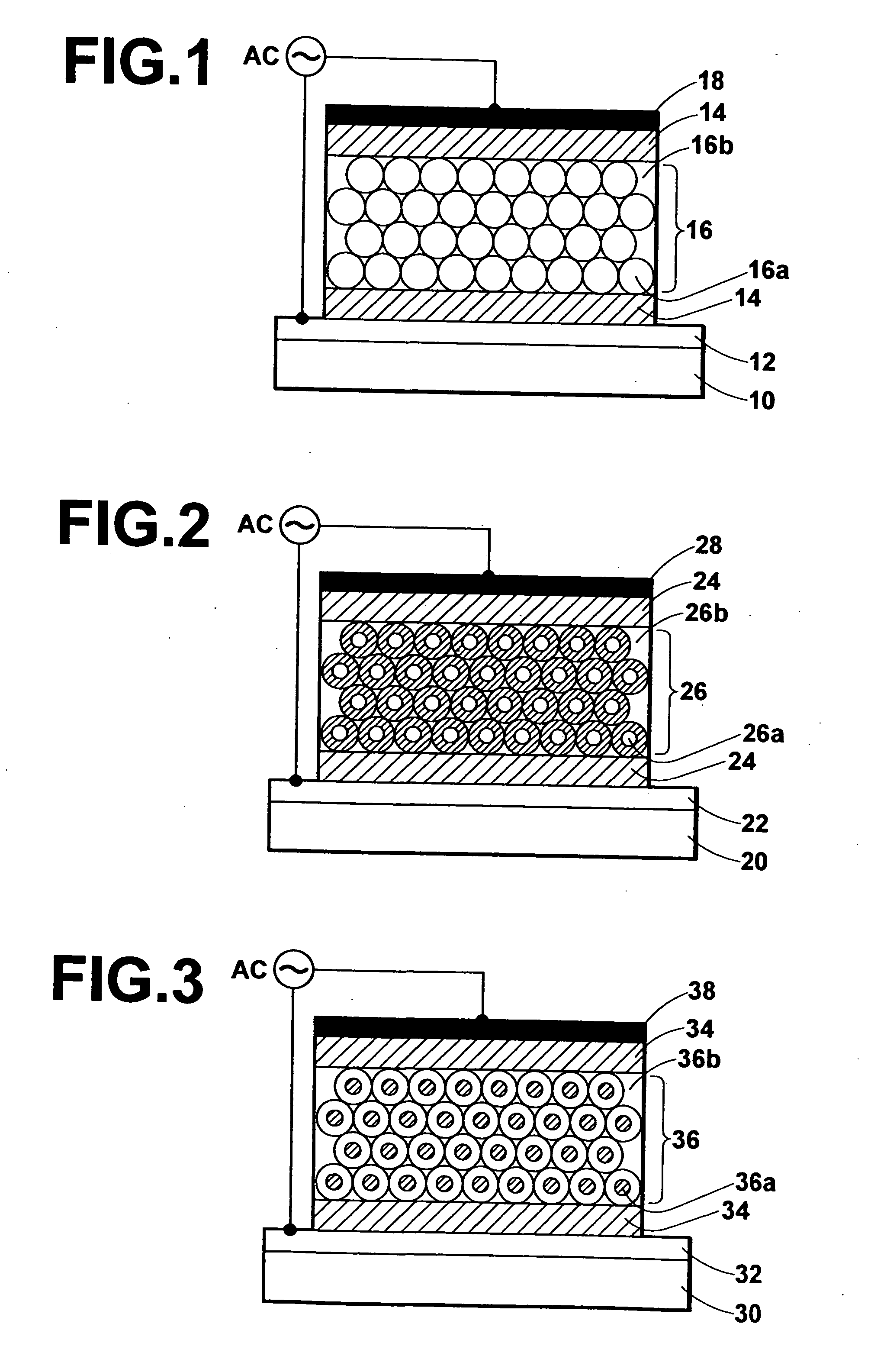
[0061]FIG. 1 is a cross-sectional view of the structure of the AC-driven electroluminescent element according to the first embodiment of the present invention. As illustrated in FIG. 1, a transparent electrode 12 and a first insulation layer 14 are formed on a transparent substrate 10, and a light emission layer 16 is formed on the first insulation layer 14. The light emission layer 16 is composed of fluorescent particles 16a and a filler 16b. Each of the fluorescent particles 16a is made of ZnS:Mn, and has a diameter of about 3 micrometers. The spaces between the fluorescent particles 16a are filled with the filler 16b. In FIG. 1 (also in FIGS. 2 through 4), the thickness of the light emission layer 16 and the sizes of the fluorescent particles 16a are exaggerated for clarification. In this example, the filler 16b is silicone oil, which is a material exhibiting a low dielectric dissipation factor of 0.0001 during application of an AC voltage of 50 Hz. The fluorescent particles 16a ...

second embodiment

[0063]FIG. 2 is a cross-sectional view of the structure of the AC-driven electroluminescent element according to the second embodiment of the present invention. As illustrated in FIG. 2, a transparent electrode 22 and a first insulation layer 24 are formed on a transparent substrate 20, and a light emission layer 26 is formed on the first insulation layer 24. The light emission layer 26 is composed of particles 26a and a filler 26b. Each of the particles 26a is constituted by a fluorescent core made of ZnS:Mn (as a fluorescent material) and a dielectric surface coating of Y2O3 (as a dielectric material) covering the fluorescent core, and has a diameter of about 3 micrometers. The spaces between the particles 26a are filled with the filler 26b. In this example, the filler 26b is silicone oil. The particles 26a are densely arranged in the light emission layer 26 in such a manner that the particles 26a are fused with each other or in mechanical or electrical contact with each other, an...

third embodiment

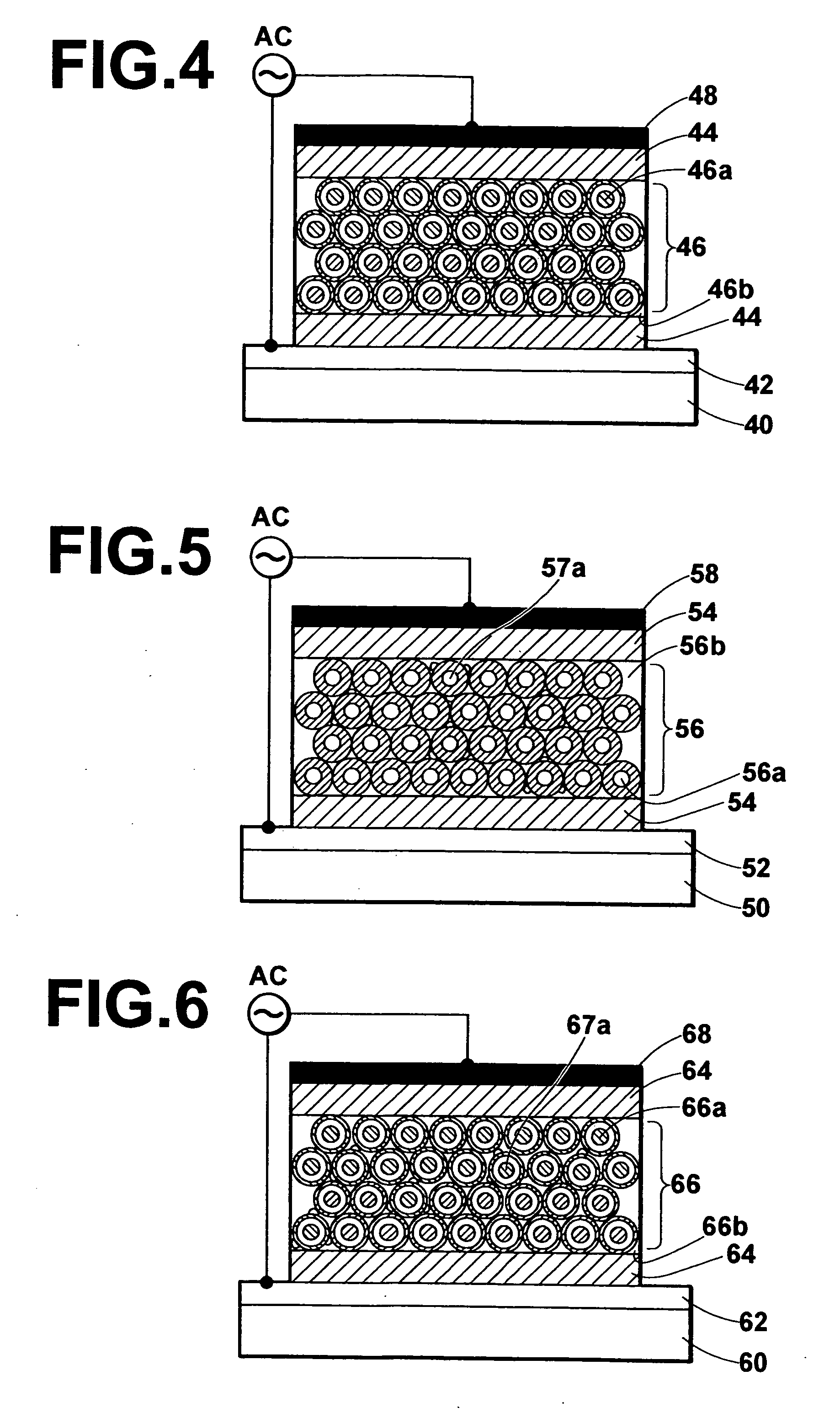
[0065]FIG. 3 is a cross-sectional view of the structure of the AC-driven electroluminescent element according to the third embodiment of the present invention. As illustrated in FIG. 3, a transparent electrode 32 and a first insulation layer 34 are formed on a transparent substrate 30, and a light emission layer 36 is formed on the first insulation layer 34. The light emission layer 36 is composed of particles 36a and a filler 36b. Each of the particles 36a is constituted by a dielectric core made of Y2O3 (as a dielectric material) and a fluorescent layer made of ZnS:Mn (as a fluorescent material) and formed over the dielectric core, and has a diameter of about 3 micrometers. The spaces between the particles 36a are filled with the filler 36b. In this example, the filler 36b is silicone oil. The particles 36a are densely arranged in the light emission layer 36 in such a manner that the particles 36a are fused with each other or in mechanical or electrical contact with each other, an...


PUM


Abstract

An AC-driven electroluminescent element includes a pair of electrodes and a light emission layer being located between the pair of electrodes and containing particles and a filler with which gaps between the particles are filled. The particles are densely arranged in the light emission layer in such a manner that the particles are fused with each other or in mechanical or electrical contact with each other, and the ratio of the volume occupied by the particles to the volume occupied by the filler in the light emission layer is 1.0 or greater. Each particle has a portion made of a fluorescent material. When the outermost surfaces of all of the particles are not made of a dielectric material, at least one insulation layer is arranged on at least one side of the light emission layer.

Description

BACKGROUND OF THE INVENTION [0001] 1. Field of the Invention [0002] The present invention relates to an alternate-current-driven (AC-driven) electroluminescent element which includes a light emission layer containing fluorescent particles and having a structure of a dispersion type, and the present invention also relates to a method for producing the above AC-driven electroluminescent element. [0003] 2. Description of the Related Art [0004] The following documents (1) to (4) disclose information related to the present invention. [0005] (1) International Patent Publication No. WO / 02 / 080626 [0006] (2) Japanese Unexamined Patent Publication No. 2000-195674 [0007] (3) Inoguchi, Toshio, “Electroluminescent Display,” first edition, published in Japanese by Sangyo Tosho on Jul. 25, 1991 [0008] (4) T. Honda et al., “Cathodoluminescence spectra of GaN powders deposited on glass substrate,” Journal of Luminescence, Vols. 102-103 (2003) pp. 173-175 [0009] Currently, electroluminescent elements...

Claims


Application Information

Patent Timeline
IPC IPC(8): C09K11/00C09K11/58H05B33/14H01J63/04H05B33/10H05B33/22
CPCH05B33/14C09K11/584
Inventor TAKAHASHI, KENJIFUJIMOTO, HIROSHIIKADA, TOMOTAKE
Owner FUJIFILM CORP
Why Eureka
Try Eureka