Visual display unit illumination

a technology for visual display units and illumination, applied in the manufacture of electric discharge tubes/lamps, discharge tubes luminescnet screens, instruments, etc., can solve the problems of small computing devices of personnel, equal display areas of such devices, and use of full-size keyboards, so as to avoid the effect of decreasing intensity

Active Publication Date: 2005-03-24
APTIV TECH LTD
View PDF99 Cites 158 Cited by
  • Summary
  • Abstract
  • Description
  • Claims
  • Application Information

AI Technical Summary

Benefits of technology

According to an alternative embodiment of the present invention, the said prescribed thickness of the emissive sheet is reduced as a function of distance from a said light source.
The above configurations of the said feature distribution and emissive sheet thickness both provide a means of outputting a uniform light intensity, avoiding decreasing intensity with distance from the light source.

Problems solved by technology

However, the advent of yet smaller personnel computing devices, i.e., the palmtop or Personal Digital Assistant (PDA) has precluded the use of a full-size keyboard.
Furthermore, the display areas of such devices are equally restricted by their diminutive size.
However, light can be extracted or caused to ‘leak’ out from the light guide surface by forming therein scratches, undulations, or any other means of locally altering the critical angle for total internal reflection.
Transflective display constructions are employed in most PDA devices due to their reduced power storage capabilities and their need to function in outdoor and / or bright ambient light conditions.
PDA devices may be generally characterised therefore as having a shortage of display / input interface area and a limited ability to operate power intensive devices such as high luminance emissive displays.
However, the addition of a further display screen overlaying the existing screen of a PDA type device results in a significantly darkened combined display.
This is due in part to the intrinsic attenuation of light passing through the additional layers of the additional display and to the unpracticality of increasing the backlighting luminance due to the power constraints discussed above.

Method used


Image

  • Visual display unit illumination
  • Visual display unit illumination
  • Visual display unit illumination

Examples


Embodiment Construction

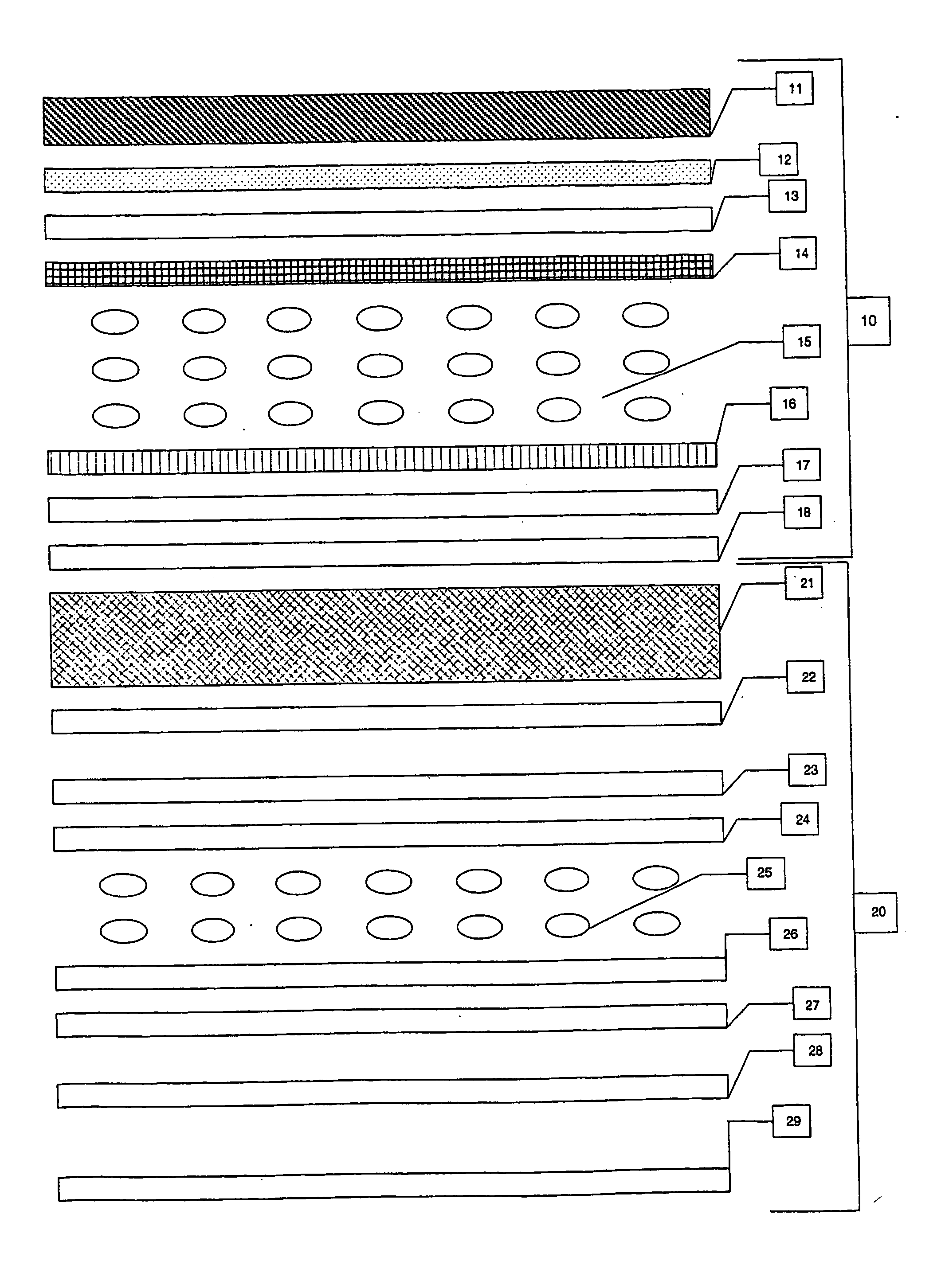
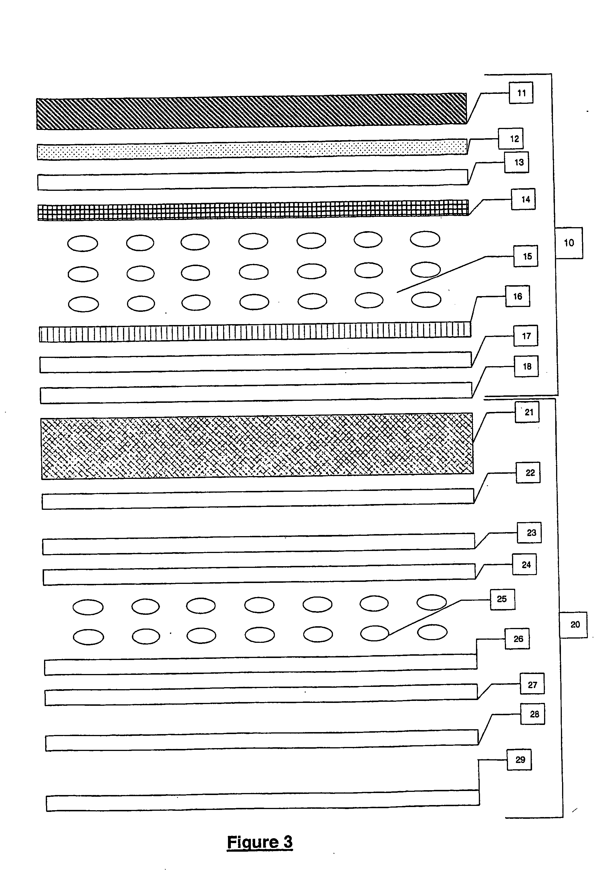
FIGS. 1-7 illustrate preferred embodiments of the present invention in the form of a personal digital assistant (PDA), or parts thereof. However, it should be appreciated that the present invention is equally applicable to a variety of visual display units including portable and / or hand held computing means such as mobile phones, watches, calculators, data loggers, and such like and these are defined for the purposes of the specification as being encompassed by the invention.

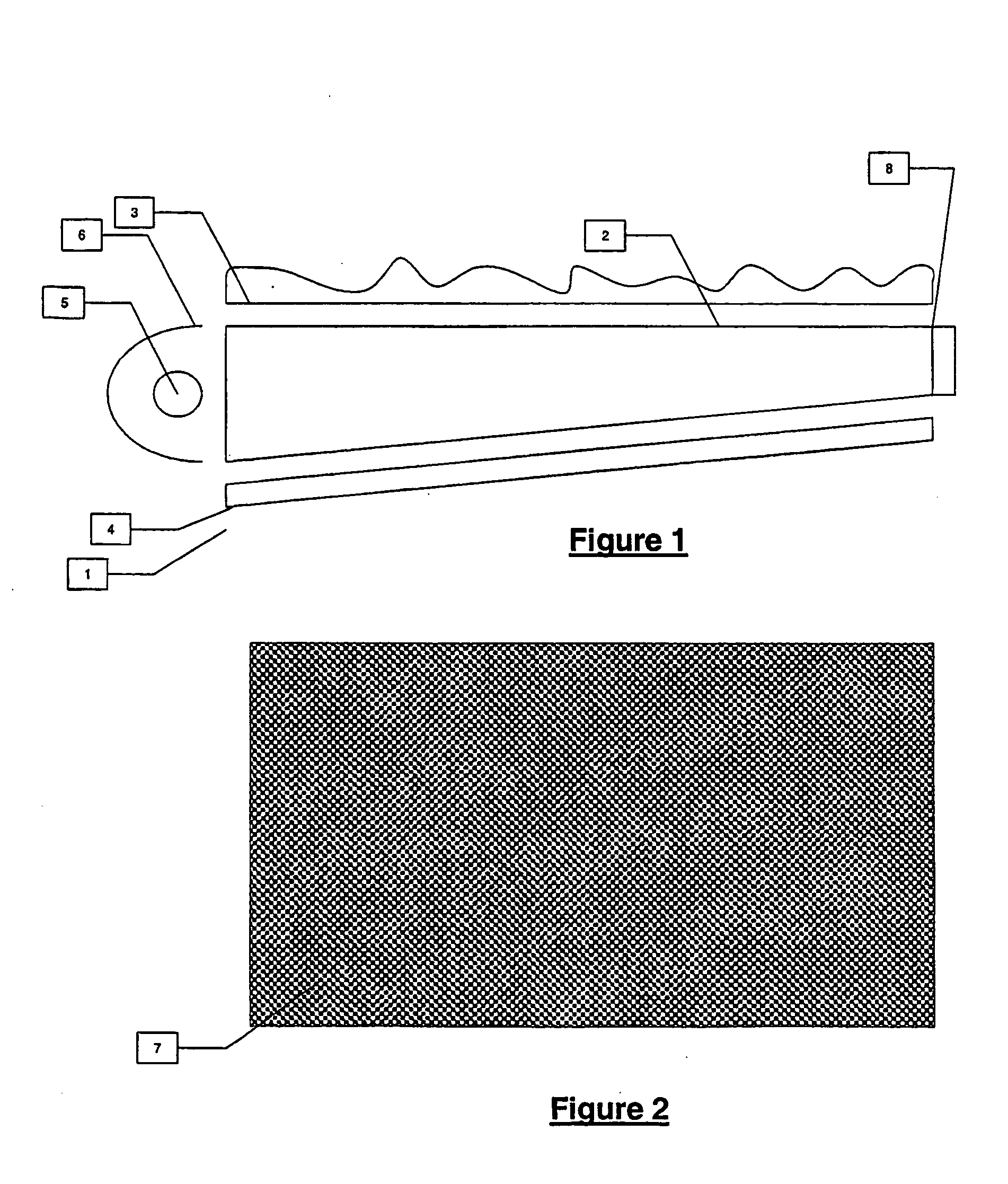
Existing devices incorporating portable visual display units such as PDAs are severely restricted in their power consumption requirements of their components due to the limited battery storage capacities. Consequently, there is widespread adoption of transflective displays and the use of light pipes or light guides as part of the back lighting assembly. FIG. 1 shows a typical back light assembly (1) used in notebook type computers incorporating a light guide (2) in the form of a rectangular clear acrylic sheet ...


PUM

PropertyMeasurementUnit
transparentaaaaaaaaaa
thicknessaaaaaaaaaa
critical angleaaaaaaaaaa

Abstract

A method of adapting a visual unit having a first screen (10) in a first focal plant by the addition of one or more at least partially transparent display screens (20) at least partially overlapping said first screen (10) and located in focal planes distinct from said first focal plane, characterised in that an at least partially transparent emissive layer (21) is provided between said first screen (10) and at least one said additional display screen (20).

Description

TECHNICAL FIELD The present invention relates to a means for illuminating visual display units, particularly portable computing means including the genre known as Personal Digital Assistants (PDA). BACKGROUND ART The relentless tide of technological improvements in computing has inexorably led to ever more powerful computers, of ever-smaller volumes. This has given rise in recent times, to successively smaller incarnations of the Personnel Computer (PC), i.e., the desktop, laptop and notebook computer. Although of reduced physical dimensions in comparison to its predecessor, each has retained a conventional keyboard as its primary means of data input. However, the advent of yet smaller personnel computing devices, i.e., the palmtop or Personal Digital Assistant (PDA) has precluded the use of a full-size keyboard. Furthermore, the display areas of such devices are equally restricted by their diminutive size. PDAs are typically the size of a user's hand, requiring the user interfac...

Claims


Application Information

Patent Timeline
Patent Type & Authority Applications(United States)
IPC IPC(8): G02F1/1335G02F1/13357G02F1/1347G02F1/137
CPCG02F1/133555G02F1/13718G02F1/13471G02F1/133603G06T15/08G06F3/1423G06T11/60
Inventor BELL, GARETH PAULENGEL, GABRIEL DAMON
Owner APTIV TECH LTD
Why Eureka
Try Eureka