Polymer ptc thermistor and temperature sensor

a thermistor and polymer technology, applied in the direction of positive temperature coefficient thermistors, instruments, heat measurement, etc., can solve the problems of poor contact, oxidation gradually occurring, interrupting the current passage, etc., and achieve the effect of clear measurement of the temperatur

Inactive Publication Date: 2005-03-24
TYCO ELECTRONICS RAYCHEM KK
View PDF2 Cites 31 Cited by
  • Summary
  • Abstract
  • Description
  • Claims
  • Application Information

AI Technical Summary

Benefits of technology

[0021] The thermal expansion temperature, that is, a temperature at which the conductive paths are interrupted, can be arbitrarily set by changing the composition of the conductive polymer or adjusting the amount of carbon black. Thus, by setting the thermal expansion temperature of the conductive polymer at a certain value, it is decided that the temperature of an object is lower than the certain value when current passes through the two electrodes and it is decided that the temperature exceeds the certain value when the current is interrupted. In this way, by using the polymer PTC thermistor of the present invention as a temperature sensor element, it is possible to clearly measure a temperature while narrowing a target temperature range.
[0022] For example, the polymer PTC thermistor is mounted on the circuit board of each kind of electrical equipment, the polymer PTC thermistor of the present invention having the conductive polymer whose thermal expansion temperature is set in consideration of an upper limit temperature permitting normal operations of the circuit board. Thus, the circuit is interrupted in the event of abnormal heat on the board, thereby protecting the electrical equipment.

Problems solved by technology

Thus, oxidation gradually occurs over time.
Such oxidation considerably develops particularly between the conductive polymer 101 and the nickel foils 102c and 103c and becomes a factor causing a poor contact and interrupting the passage of current, thereby affecting the performance of the polymer PTC thermistor.
Hence, oxidation is a serious problem.
Hence, even slight oxidation is likely to cause poor contact.
Hence, such a configuration causes a problem.

Method used


Image

  • Polymer ptc thermistor and temperature sensor
  • Polymer ptc thermistor and temperature sensor
  • Polymer ptc thermistor and temperature sensor

Examples


embodiment 1

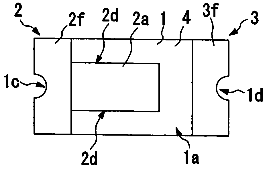
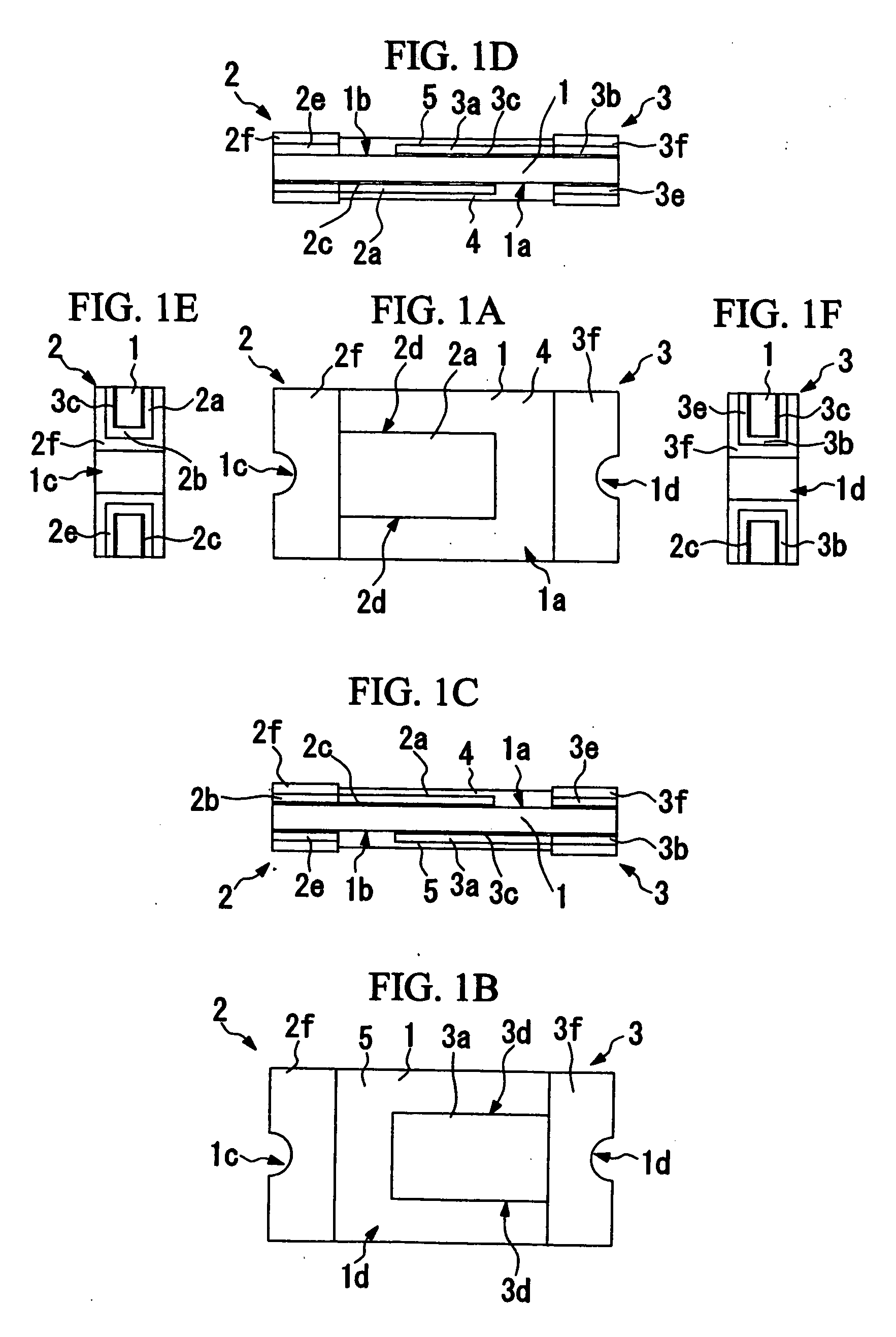
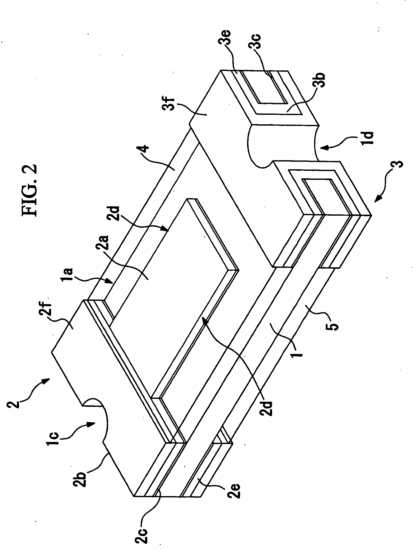
[0029] Referring to FIGS. 1 to 3, Embodiment 1 of the present invention will be described below. FIG. 1A is a plan view showing a polymer PTC thermistor according to the present embodiment. FIG. 1B is a back view, FIG. 1C is a front view, FIG. 1D is a rear view, FIG. 1E is a left side view, and FIG. 1F is a right side view. FIG. 2 is a perspective view showing the polymer PTC thermistor according to the present embodiment.

[0030] The polymer PTC thermistor is used, for various kinds of electrical equipment, as a temperature sensor element aimed at protecting an overheated circuit board. In the drawings, reference numeral 1 denotes a conductive polymer, reference numerals 2 and 3 denote electrodes joined to the conductive polymer 1, and reference numerals 4 and 5 denote nonconductive resin films for covering the electrodes 2 and 3, which are provided between the conductive polymer and the resin films 4 and 5.

[0031] The conductive polymer 1 is rectangular in plan view and is shaped l...

embodiment 2

[0052] Referring to FIG. 4, Embodiment 2 of the present invention will be described below. FIG. 4A is a plan view showing a polymer PTC thermistor according to the present embodiment. FIG. 4B is a back view, FIG. 4C is a front view, FIG. 4D is a rear view, FIG. 4E is a left side view, and FIG. 4F is a right side view. The constituent elements described in Embodiment 1 are indicated by the same reference numerals and the explanation thereof is omitted.

[0053] The present embodiment is different from Embodiment 1 in the configurations of electrodes 12 and 13. The electrode 12 is constituted of a copper electrode strip 12a provided along a side 1a of a conductive polymer1, a copper electrode strip 12b provided along the other side 1b, a base 12c provided over the electrode strips 12a and 12b on one end of the conductive polymer 1, and nickel foils 12d respectively disposed between the conductive polymer 1 and the electrode strips 12a and 12b.

[0054] The electrode 13 is similar in struc...

embodiment 3

[0062] Referring to FIG. 5, Embodiment 3 of the present invention will be described below. FIG. 5A is a plan view showing a polymer PTC thermistor according to the present embodiment. FIG. 5B is a back view, FIG. 5C is a front view, FIG. 5D is a rear view, FIG. 5E is a left side view, and FIG. 5F is a right side view. The constituent elements described in the above embodiments are indicated by the same reference numerals and the explanation thereof is omitted.

[0063] The present embodiment is different from the above embodiments in the configurations of electrodes 22 and 23. The electrode 22 is constituted of a copper electrode strip 22a provided along a side 1a of a conductive polymer 1, a base 22b which is connected to the electrode strip 22a and is provided on one end of the conductive polymer 1, and a nickel foil 22c disposed between the conductive polymer 1 and the electrode strip 22a.

[0064] The electrode 23 is similar in structure to the electrode 22. The electrode 23 is cons...


PUM

PropertyMeasurementUnit
thicknessaaaaaaaaaa
thicknessaaaaaaaaaa
thicknessaaaaaaaaaa

Abstract

The present invention relates to a polymer PTC thermistor and a temperature sensor using the same. The polymer PTC thermistor, including a conductive polymer 1 having PTC characteristics and electrodes 2 and 3 joined to the conductive polymer 1, characterized in that the electrodes 2 and 3 are provided along two sides 1a and 1b of the plate-like conductive polymer 1 and are separated from the edges of the sides 1a and 1b, and resin films 4 and 5 are formed which cover the sides 1a and 1b so as to wrap the electrodes 2 and 3.

Description

TECHNICAL FIELD [0001] The present invention relates to a polymer PTC thermistor and to a temperature sensor using the same. BACKGROUND ART [0002] A polymer PTC thermistor is a device which interrupts the passage of current by using a positive resistance temperature characteristic, that is, a PTC (Positive Temperature Coefficient) of a conductive polymer which is varied in conductivity due to thermal expansion. [0003] Referring to FIG. 6, an example of the polymer PTC thermistor will be described below. FIG. 6 is a perspective view showing a conventional polymer PTC thermistor. In FIG. 6, reference numeral 101 denotes a conductive polymer, reference numerals 102 and 103 denote electrodes joined to the conductive polymer 101, and reference numerals 104 and 105 denote nonconductive resin films for covering the electrodes 102 and 103, which are provided between the conductive polymer and the resin films 104 and 105. [0004] The conductive polymer 101 is rectangular in plan view and is s...

Claims


Application Information

Patent Timeline
Patent Type & Authority Applications(United States)
IPC IPC(8): H01C7/02G01K7/22H01C1/14
CPCH01C1/1406G01K7/22H01C7/02
Inventor KOYAMA, HIROYUKI
Owner TYCO ELECTRONICS RAYCHEM KK
Why Eureka
Try Eureka