Lens assembly with integrated focus mount and CRT coupler

a technology of lens assembly and focus mount, which is applied in the field of lens assembly, can solve the problems of shortened crt life, significant image distortion on the television screen, and undesirable heat on the lens assembly, and achieve the effects of reducing costs and complexity, convenient mechanical methods, and reducing the number of parts

Inactive Publication Date: 2005-03-24
3M INNOVATIVE PROPERTIES CO
View PDF18 Cites 6 Cited by
  • Summary
  • Abstract
  • Description
  • Claims
  • Application Information

AI Technical Summary

Benefits of technology

[0006] Preferably, the focus mount and the CRT coupler are integrally molded from a polymeric or other material or materials which can withstand the temperatures inside a projection television cabinet, meet the strength requirements to mount the CRT to the lens assembly and the entire CRT / lens assembly to a chassis of the cabinet structure of the projection television and, in certain embodiments, withstand any undesirable chemical reaction which might be caused by coolant fluid associated with the assembly. One advantage of an integrally formed coupler and focus mount can be the elimination of any flaking of the coating used to create the black finish inside the coupler. Various integral constructions of the focus mount and CRT coupler are possible and may include the use of multiple types of materials, such as metals, plastics, ceramics, etc., and various manufacturing techniques. The integral focus mount and CRT coupler may, for example, be formed of a co-molded or over-molded construction of multiple materials (e.g., metal and / or nonmetal) depending on the combined properties needed or desired in the resulting construction. As another possible alternative, the integral focus mount and coupler may be formed with metal injection molding techniques, such as thixomolding or made of aluminum or other metal material through the die casting process.
[0007] In another aspect of the invention, a generally tubular element, separate from the CRT coupler, may be used to receive a coolant fluid located generally between the CRT and the second optical lens element (e.g., a “C” lens element). This generally tubular element may be configured as a flexible bladder formed of a resilient material which expands to accommodate expansion of the coolant fluid when heated by the CRT. In this manner, the bladder may include a fill port for introducing the coolant fluid, but need not include a conventional and separate expansion bladder as typically used in couplers formed separately from an aluminum casting. In addition, the bladder keeps the fluid isolated from the coupler material which allows the opportunity to use additional materials for the coupler.
[0008] In another aspect of the invention, a flange may be positioned between the CRT and the CRT coupler and may include at least one angled portion configured to set a Scheimpflug angle at which the CRT is adapted to be mounted relative to the longitudinal axis. In the case in which the flexible bladder is not used, the flange may receive a seal for sealing the space between the CRT coupler and the CRT which will receive the coolant fluid. The seal may be generally U-shaped in cross section in order to seal both sides of the flange. It is also possible to accomplish this sealing by using two separate seals instead of a U-shaped seal. The use of a separate flange which sets the Scheimpflug angle reduces costs and complexity relative to, for example, incorporating a Scheimpflug angle in the coupler itself. In the case in which the generally tubular member (e.g., the flexible bladder) is not used, the CRT coupler may include a port for introducing the coolant fluid into the space between the CRT coupler and the CRT. In that case as well, a separate expansion bladder may be introduced through the fill port or other port in the CRT coupler and configured to expand upon heating of the coolant fluid by the CRT. A clamp plate may be used to secure the second optical lens (e.g., a “C” lens element), with threaded fasteners, spring clips, or other manners of securement. An advantage to integrating the focus mount and coupler is to provide more accurate positioning of the second optical lens element (e.g., the “C” element) to the first optical lens element (e.g., an A / B lens group). Another advantage to integrating the focus mount and coupler is that the sealing surface(s) can have a surface finish that is very suitable for sealing with no secondary machining operations necessary. Still another advantage is that it can easily provide a mechanical method to align the “C” element to the coupler in a rotational manner. This method ensures better consistency in the lens performance.
[0009] According to another inventive aspect, this clamp plate can include an opening or mask that serves as a light stop for the “C” element. Such an opening or mask can alternatively or also be formed in the coupler or in a separate piece secured against the coupler. The two masks can be used independently or together. A benefit of this feature is to eliminate the need to paint the “C” element to create a light stop. According to another inventive aspect, this clamp plate can include a generally rectangular opening or mask adapted to receive light from the CRT and transmit the light in the form of a generally rectangular-shaped image to the screen. Another correspondingly shaped and aligned mask may be formed directly in the coupler. Alternatively, the other correspondingly shaped and aligned mask may be clamped in place on an opposite side of the second optical lens element. This latter alternative allows for the easy addition of such a mask or masks to the overall assembly. The generally rectangular shape may have one of the standard format ratios of length to width for projection televisions, e.g., 4:3 or 16:9. This feature serves to improve the contrast of the optical system by reducing unwanted light. As contemplated herein such a generally rectangular mask may be formed by a separate member located adjacent to one of the lens elements in the assembly or system, or it may be formed by a coating on the lens or lenses.

Problems solved by technology

Such heat can have undesirable effects on the lens assembly, such as changes in the focus of the lens assembly.
This can lead to significant image distortions on the television screen.
In addition, such heat can lead to extreme temperature gradients on faceplate of CRT possibly causing a shortened CRT life.
Various problems or drawbacks with current systems utilizing separate die cast aluminum couplers include the increased number of parts and increased assembly.
In addition, the use of increased numbers of components in the overall assembly necessarily leads to an increase in tolerance stack up and, therefore, less overall dimensional accuracy in the assembled product.
In the case of a lens and CRT assembly for use in a projection television this may lead to additional distortion in the image projected onto the television screen.
Another disadvantage in using a CRT coupler with nonreflective surface finish such as black paint or other coating is that this finish can flake off into the coolant fluid and degrade the image performance of the lens system.
Another disadvantage in the current system is the need to perform a secondary machining process to the sealing areas of the coupler due to the rough surface finish of a die cast part.
Still another disadvantage is the fact that the coupler does not contain any way to rotationally orient the “C” lens element.

Method used


Image

  • Lens assembly with integrated focus mount and CRT coupler
  • Lens assembly with integrated focus mount and CRT coupler
  • Lens assembly with integrated focus mount and CRT coupler

Examples


Embodiment Construction

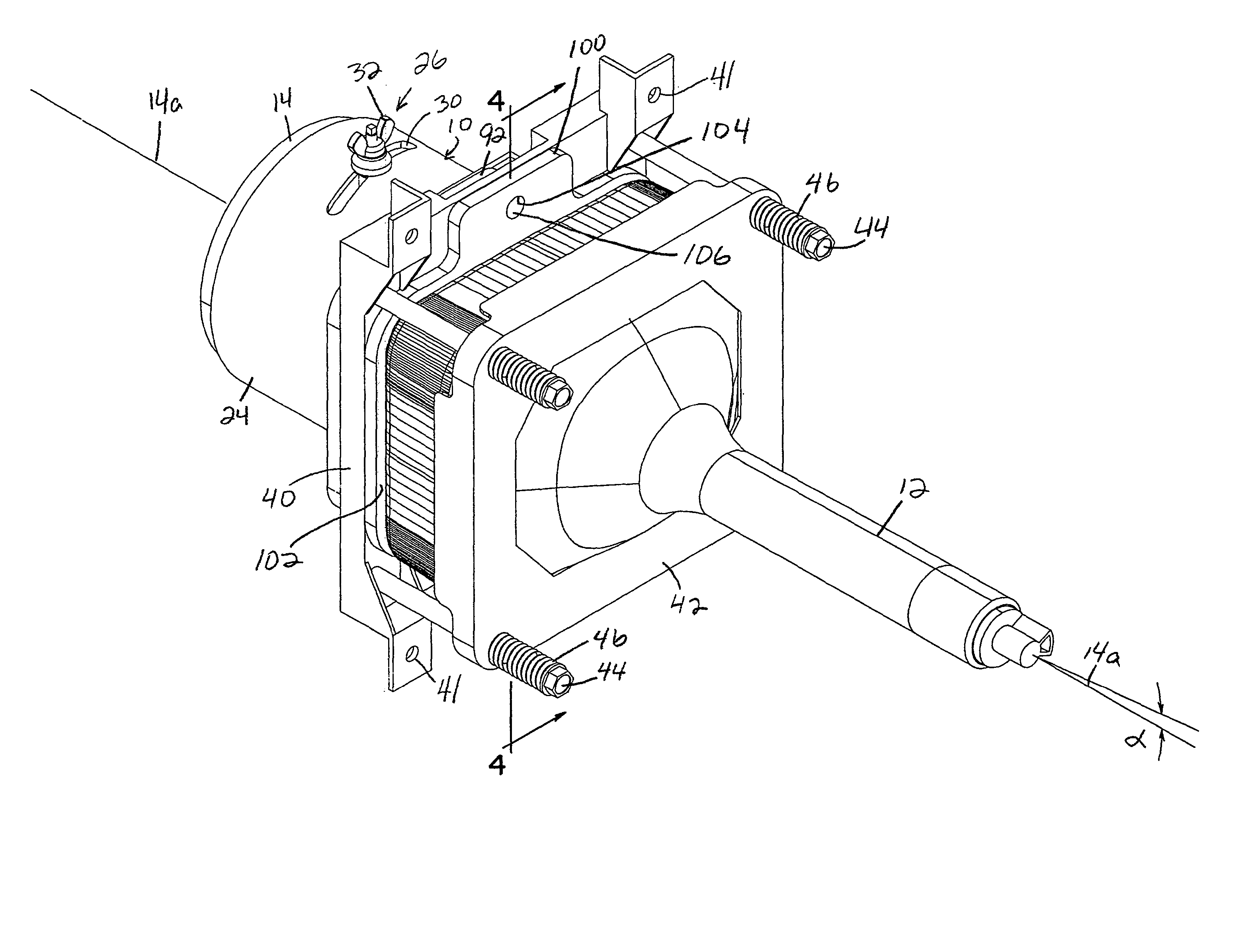
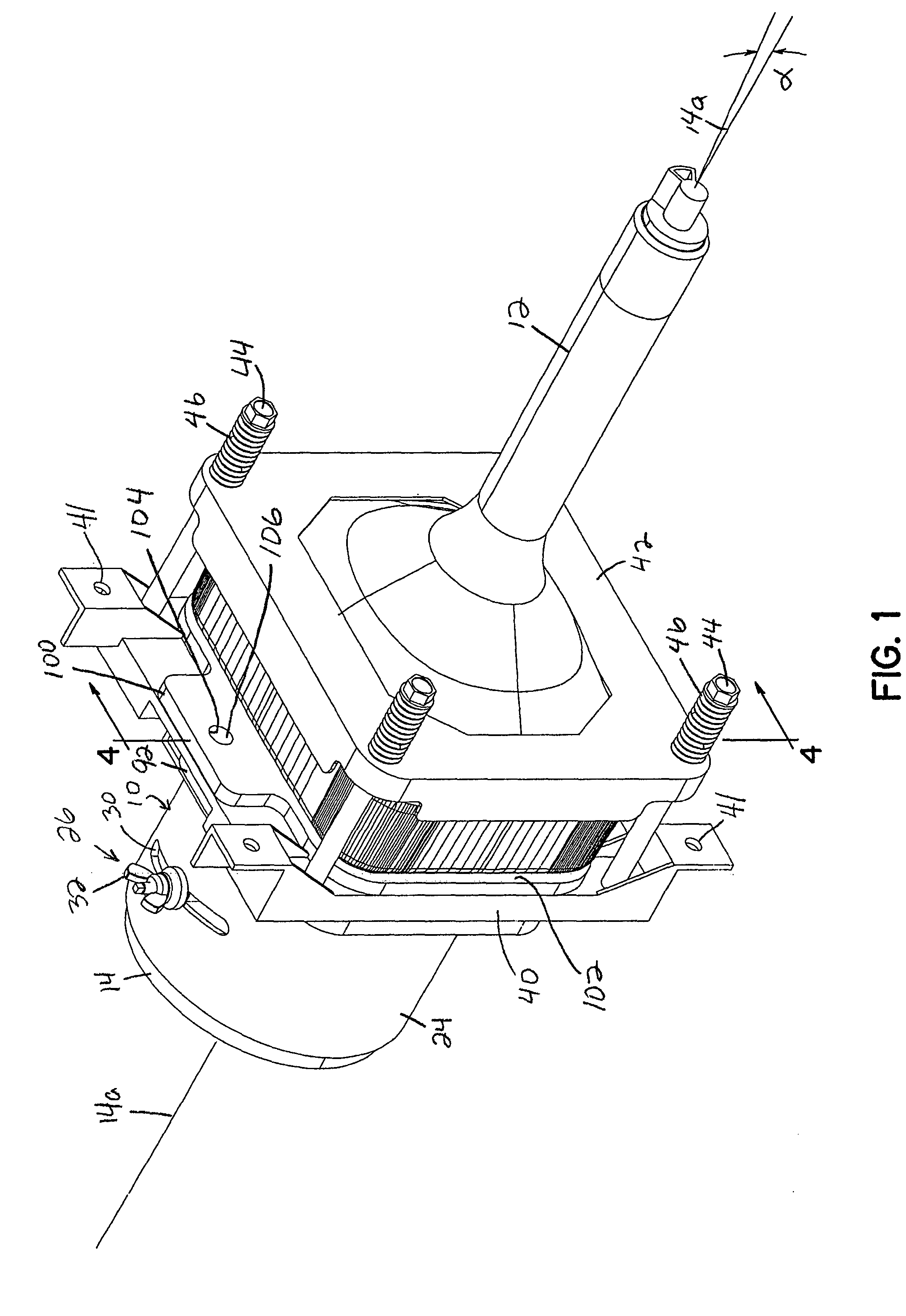
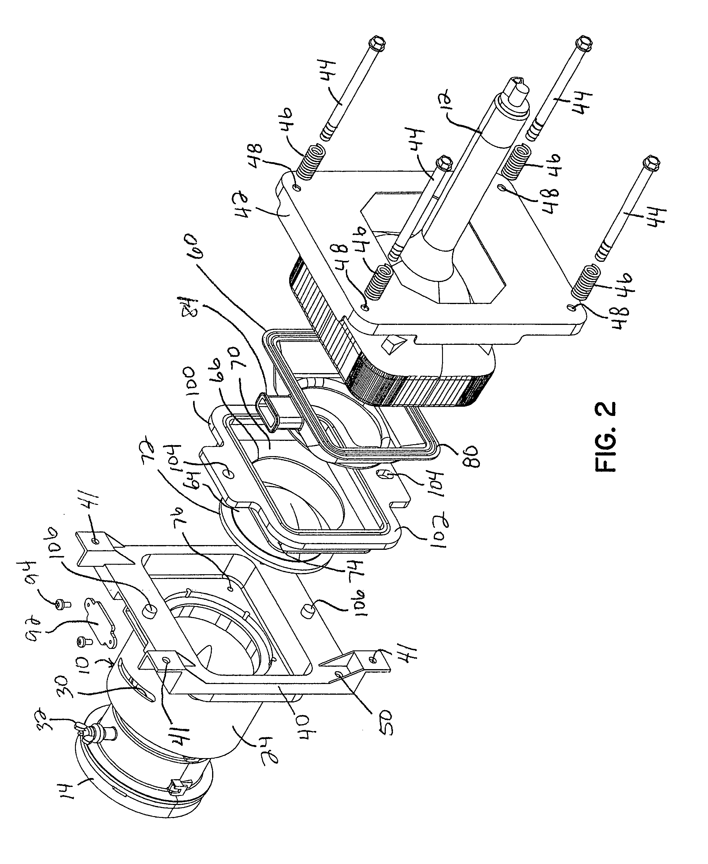
[0030]FIGS. 1-4 illustrate a first embodiment of the invention. Specifically, a lens assembly 10 is connected to a CRT 12 and includes a tubular lens mount 14 having a longitudinal axis 14a and at least a first optical lens element mounted therein along the longitudinal axis 14a. In this embodiment, multiple lens elements 16, 18, 20 are mounted within the tubular lens mount 14 and may comprise separate “A” and “B” lens elements as are conventionally used in projection television lens systems. The tubular lens mount 14 is mounted within a tubular focus mount 24 extending along the same longitudinal axis 14a and adjustable fastening and locking structure 26 connects the lens mount 14 to the focus mount 24 allowing a focus position to be obtained and locked in place between the lens mount 14 and the focus mount 24. This fastening and locking structure 26 may comprise a slot 30 in the focus mount 24 and conventional threaded fastening and clamping elements 32 coupled with the lens mount...


PUM


Abstract

A lens assembly adapted to be connected to a CRT and affixed to mounting structure in a projection television cabinet. The lens assembly includes a tubular lens mount having a longitudinal axis and at least a first optical lens element mounted along the longitudinal axis. A tubular focus mount extends along the longitudinal axis and fastening and locking structure connects the lens mount to the focus mount after a focus mount position is obtained. A CRT coupler is formed integrally with the focus mount and includes structure for securing a CRT and for securing the coupler to the mounting structure within the television cabinet. A second optical lens element is mounted to the CRT coupler. A flexible bladder may be used to contain coolant fluid between the CRT and the coupler. A flange may be provided to set a Scheimpflug angle between the CRT and the coupler. A clamp plate for the second optical lens element may include a generally rectangular opening providing a 4:3 or 16:9 mask for the image transmitted by the CRT.

Description

FIELD OF THE INVENTION [0001] The present invention generally relates to lens assemblies used to project images onto projection television screens and, more particularly, to the manner of assembling and mounting such lens assemblies or systems within the cabinet of the projection television. BACKGROUND OF THE INVENTION [0002] Projection televisions typically use cathode ray tubes (CRTs) which display an image on a glass faceplate. That image is projected through a coupler and lens assembly onto a screen of the television. The coupler is typically formed as a separate component of die cast aluminum and serves to couple the CRT to the lens assembly and also to secure the coupler / lens assembly as a unit to appropriate mounting structure within the television cabinet. In rear projection type televisions, three such CRT units are used to project the same image in the three primary colors onto a mirror with the image being reflected and magnified onto the viewing screen. [0003] A “C” lens...

Claims


Application Information

Patent Timeline
Patent Type & Authority Applications(United States)
IPC IPC(8): G02B13/16H04N5/74
CPCH04N9/3141G02B13/16H04N5/74
Inventor GLASSBURN, ROBIN S.FULKERSON, E. GREGORYLARSON, MICHAEL B.SNIVELY, DAVID M.KEYES, DONALD LEEDAWES, BRIAN L.MEISER, DANIEL G.
Owner 3M INNOVATIVE PROPERTIES CO
Why Eureka
Try Eureka