Electrical ionizer

a technology of electric ions and ionizers, applied in the field of electric ions, can solve the problems of axial fans having a number of problems, upset the ionization balance, and static charges of a few hundred volts can have disastrous effects on semiconductor devices such as micro-processor chips, so as to improve the air flow, prevent gaps in the air flow, and improve the effect of ionization balan

Inactive Publication Date: 2005-03-24
MEECH STATIC ELIMINATORS LTD
View PDF12 Cites 13 Cited by
  • Summary
  • Abstract
  • Description
  • Claims
  • Application Information

AI Technical Summary

Benefits of technology

[0016] The flow of air thus produced is generally a highly uniform and laminar beam of air along the entire length of the fan. The use of such a fan in an ionizer is therefore highly advantageous in preventing gaps in the air flow and maintaining a consistent velocity of air to ensure good ion balance.
[0017] The use of a crossflow fan not only permits an improvement in the air flow, it also enables the operating mechanism to be contained within a simple “teardrop” profile. It also makes it possible for most of the operative parts of the device, f

Problems solved by technology

In the electronics industry, however, and in particular, in clean rooms, static charges of a few hundred volts can have disastrous effects on semiconductor devices such as micro-processor chips.
Axial fans have a number of problems.
This can lead to ion recombination which can in turn upset the ionization balance, and is more likely to lead to contamination.
Air flow velocities can vary from fan to fan when a series of axial fans is used, and gaps or areas of overlap can arise in the airflow

Method used


Image

  • Electrical ionizer
  • Electrical ionizer
  • Electrical ionizer

Examples


Embodiment Construction

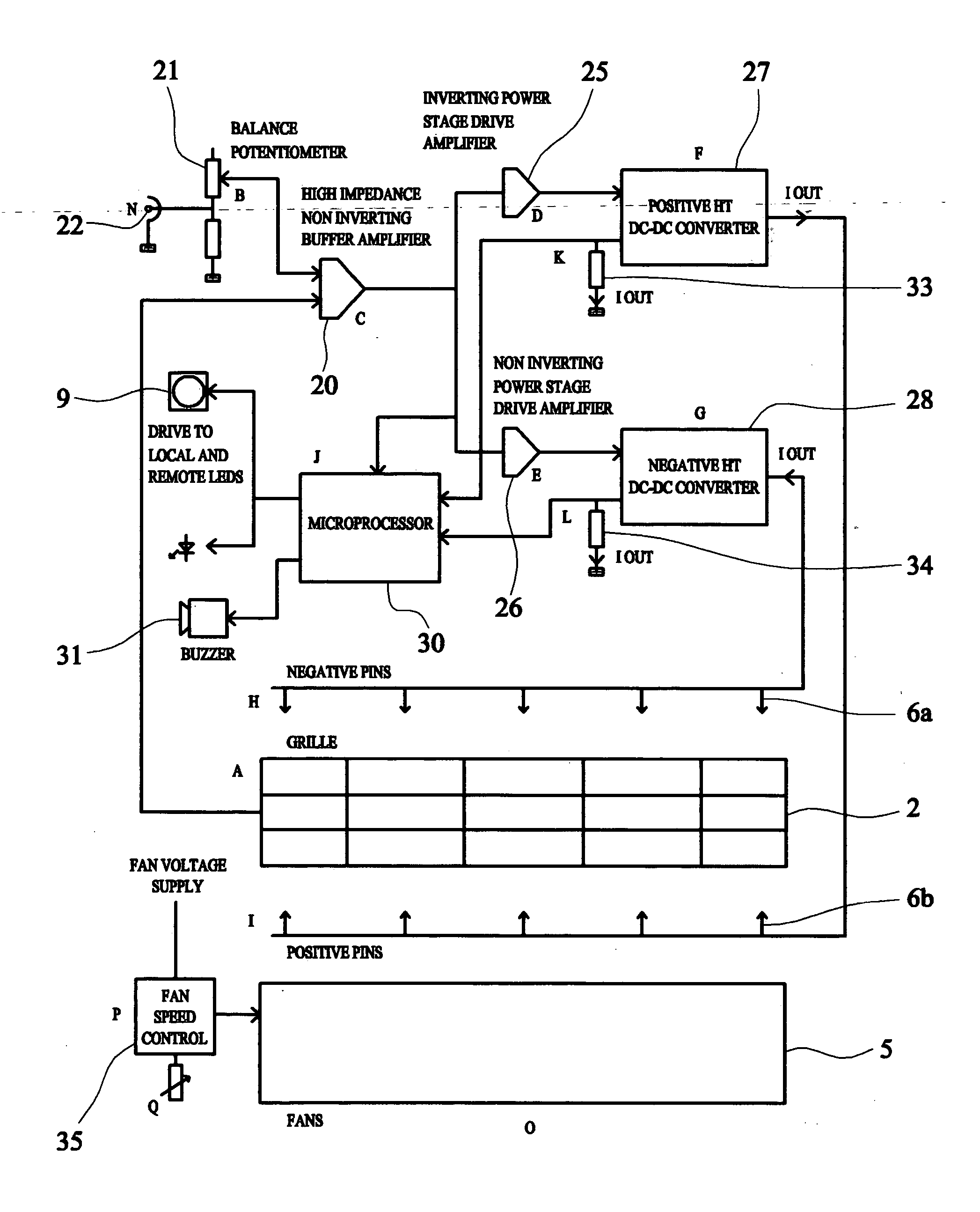
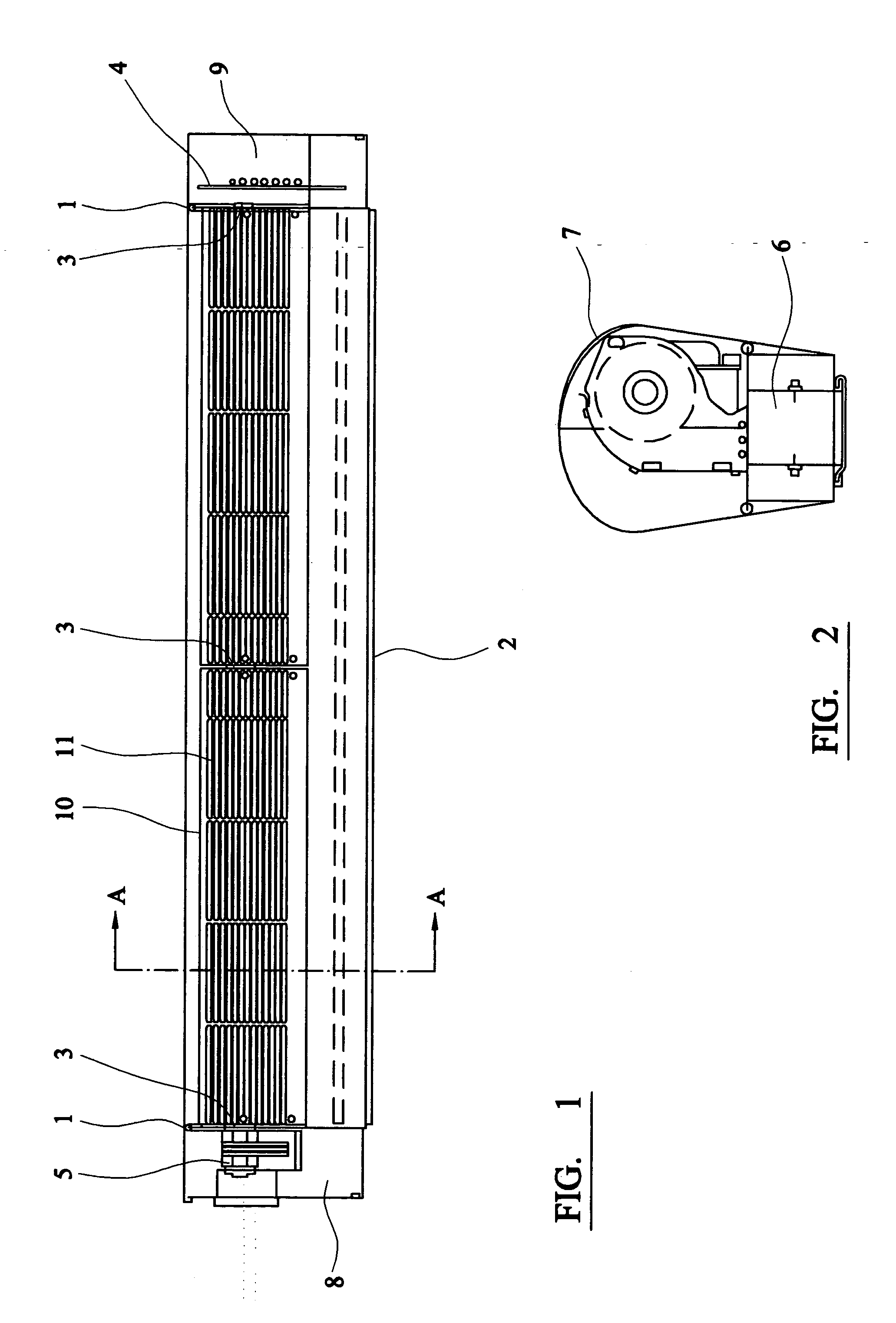
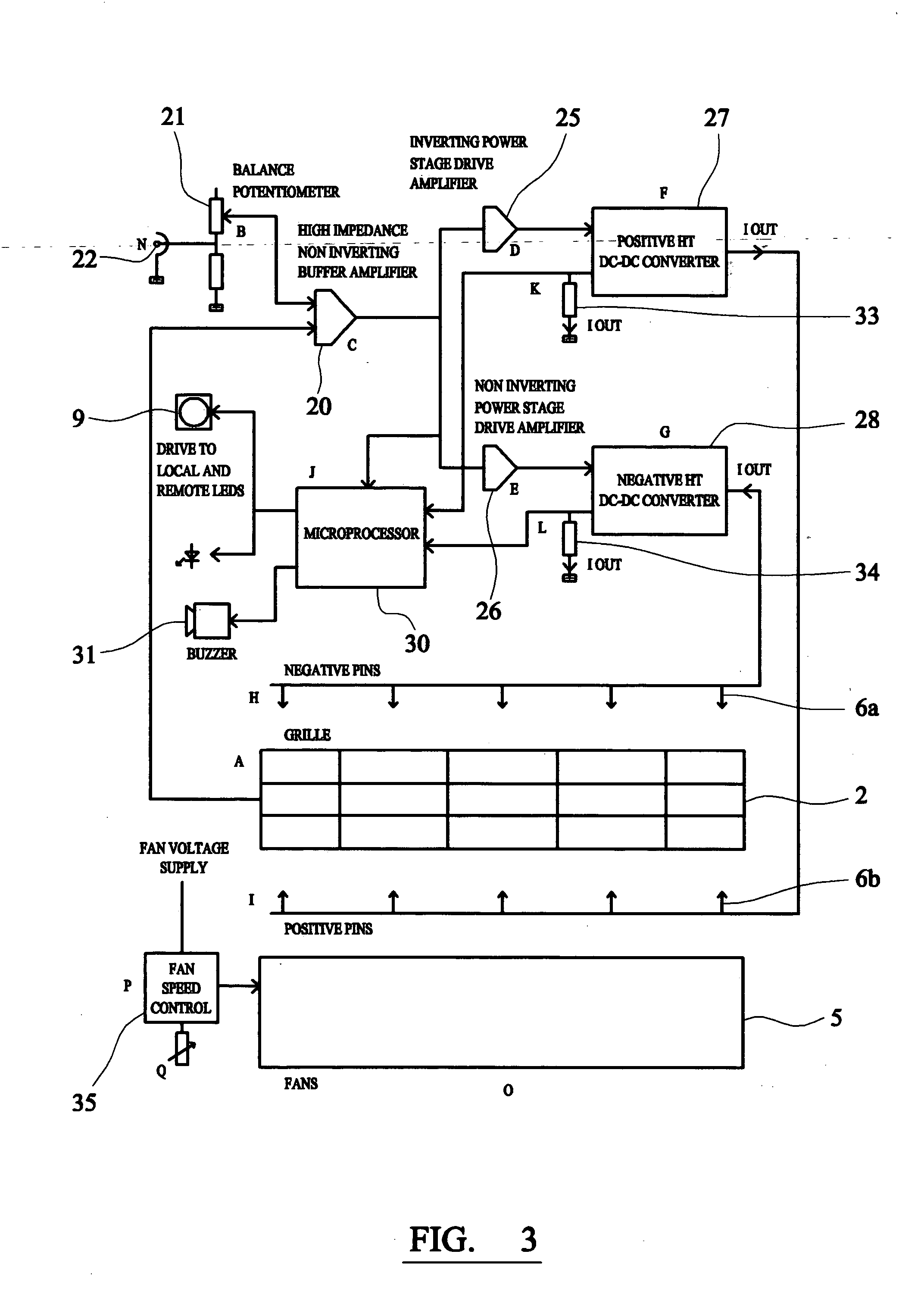
[0027]FIGS. 1 and 2 show an electrical ionizer according to one embodiment of the invention that is suitable for use in a clean room environment. The ionizer comprises a crossflow fan having an impeller 10, driven by an impeller motor 5, and housed within a casing 7. The casing is fabricated from stainless steel (other materials suitable for use in a clean room environment can also be used) and has a “teardrop” profile as is evident from FIG. 2. This profile allows the ionizer to be positioned in the laminar downdraft air flow encountered in clean rooms without unduly disturbing this airflow.

[0028] Air enters the unit through an inlet 11, and is expelled through an exit opening 12. Bulkheads 1 are provided at each end of the unit and are sealed to the outer casing 7 by means of gaskets, so as to confine the air flow within the desired part of the unit. The Bulkheads 1 also prevent particulate contamination originating with the motor 5 and associated control electronics form enterin...


PUM


Abstract

An electrical ionizer comprising a fan (5) for producing a laminar flow of air; a positive ion emitter (6b) for ejecting positive ions into the flow of air; a negative ion emitter (6a) for ejecting negative ions into the flow of air; a positive voltage supply (27) to the positive ion emitter; a negative voltage supply (28) to the negative ion emitter; and a microprocessor (30) for controlling the positive and negative voltages to obtain a desired ion balance in the flow of air. The fan (5) is a crossflow fan, resulting in a highly uniform and laminar beam of air along the entire length of the fan, with reduced gaps in the air flow and consistent velocity of air, improving ion balance. The use of a crossflow fan also enables the operating mechanism to be contained within a simple “teardrop” profile, and for operative parts of the device, for example the motor, the bearings, and electronics such as printed circuit boards to be housed outside the air flow, thereby eliminating a possible source of contamination of the air flow. For a comparable size of ionizer enclosure, approximately twice the mass flow, at higher velocities, can be generated as a similar conventional device using axial fans, and at reduced noise levels.

Description

FIELD OF THE INVENTION [0001] The present invention relates to electrical ionizers, in particular electrical ionizers for use in “clean rooms” used for the assembly of sensitive electronic equipment, such as semiconductor devices, computer components, hard disks, LCDs, etc. BACKGROUND OF THE INVENTION [0002] Electrical ionizers are commonly used in such environments to generate ions in the air and thereby enable neutralization of surface charges. In the majority of applications, the reduction of a static charge to a few hundred volts is nominally sufficient to eliminate dust attraction. In the electronics industry, however, and in particular, in clean rooms, static charges of a few hundred volts can have disastrous effects on semiconductor devices such as micro-processor chips. In these instances it is important to ensure that the ionization delivered by a neutralization system is balanced and targeted specifically to areas where neutralization is required. In many applications, bui...

Claims


Application Information

Patent Timeline
IPC IPC(8): H01T23/00
CPCH01T23/00
Inventor FRANCIS, CHRISTOPHERHATCHER, SIMONROGERS, DAVIDSTEPHEN, DAVID
Owner MEECH STATIC ELIMINATORS LTD
Why Eureka
Try Eureka