Optical fiber for improved performance in S-, C- and L-bands

Active Publication Date: 2005-03-24
FURAKAWA ELECTRIC NORTH AMERICA INC
View PDF4 Cites 9 Cited by
  • Summary
  • Abstract
  • Description
  • Claims
  • Application Information

AI Technical Summary

Benefits of technology

The need remaining in the prior art is addressed by the present invention, which relates to optical transmission fiber suitable to support distributed Raman ampli

Problems solved by technology

The two regions are then mated in a chlorine atmosphere (or other suitable atmosphere) to form an ul

Method used


Image

  • Optical fiber for improved performance in S-, C- and L-bands
  • Optical fiber for improved performance in S-, C- and L-bands
  • Optical fiber for improved performance in S-, C- and L-bands

Examples


Embodiment Construction

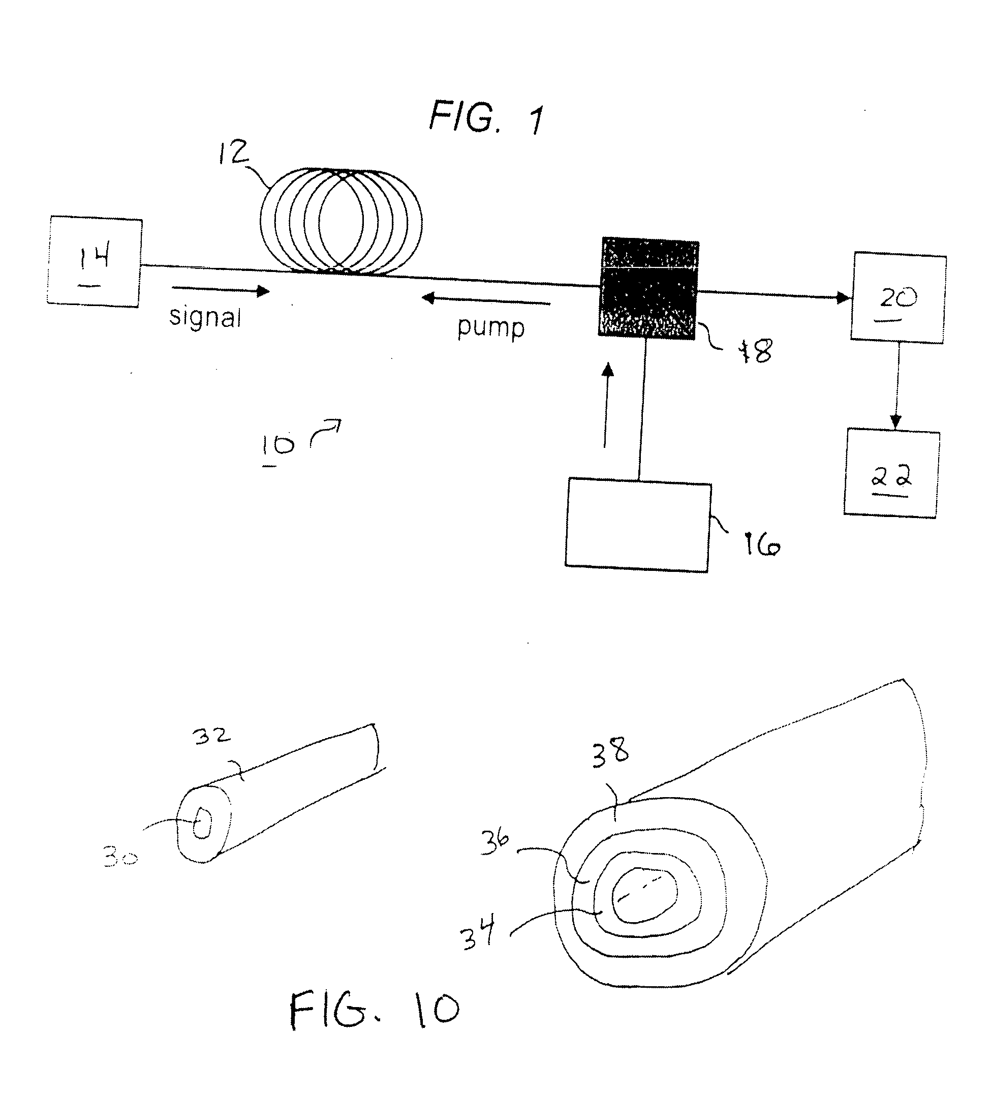
An optical fiber communication system 10 suitable for using the transmission fiber 12 of the present invention is illustrated in FIG. 1. In the particular arrangement of FIG. 1, transmission fiber 12 is formed as a distributed amplifier, dedicated to providing both transmission and amplification of an applied optical information signal I from a signal source, such as an optical transmitter 14. The length of transmission fiber 12 is typically at least 500 m, so as to allow for the optical interactions that produce Raman amplification to occur. In the particular arrangement of communication system 10, the amplifier is counter-pumped, with a Raman source 16 coupled into the core of transmission fiber 12 through a coupler 18, as shown. A dispersion compensation module 20, as discussed below, is disposed in the signal path between the output of transmission fiber 12 and an optical receiver 22. It is to be understood that this particular embodiment is exemplary only, and an arrangement u...


PUM

PropertyMeasurementUnit
Timeaaaaaaaaaa
Timeaaaaaaaaaa
Areaaaaaaaaaaa

Abstract

An improved optical fiber design has been found to exhibit a relatively low attenuation at the wavelength of 1385 nm (the “water peak”), allowing for Raman amplification to be efficient and effective at wavelengths in the S-band range of 1460 to 1530 nm. An ultra-dry process is used to mate an inner core rod (core plus surrounding trench) with a cladding tube (ring region plus cladding layers) and provide a water peak loss on the order of 0.325 dB/km. The low water peak is combined with appropriate dispersion values and zero dispersion wavelength to form a fiber that supports transmission and Raman amplification in the S-, C- and L-bands of interest for optical transmission systems.

Description

TECHNICAL FIELD The present invention relates to optical transmission fiber suitable to support distributed Raman amplification and, more particularly, to optical fiber exhibiting operating parameters compatible with generating Raman amplification in the S-band transmission region. BACKGROUND OF THE INVENTION As a result of the tremendous and continuous increase in data-intensive applications, the demand for bandwidth in communication systems has been ever-increasing. In response, the installed capacity of telecommunications operations has been largely supplanted by optical fibers that provide a significant bandwidth enhancement over the traditional copper wire-based systems. To exploit the bandwidth of optical fibers, two key technologies have been developed and used in the telecommunications industry: optical amplifiers and wavelength division multiplexers (WDMs). Optical amplifiers boost the signal strength and compensate for inherent fiber loss and other splitting and inserti...

Claims


Application Information

Patent Timeline
IPC IPC(8): G02B6/02G02B6/00G02B6/036G02F1/35H04B10/17H04B10/18
CPCC03B37/01211C03B2201/075C03B2203/22H04B10/2916G02B6/03611G02B6/03666H04B10/2563G02B6/02271
Inventor JABLONOWSKI, DONALDKALISH, DAVIDKIM, JINKEELINGLE, ROBERT JR.
Owner FURAKAWA ELECTRIC NORTH AMERICA INC
Why Eureka
Try Eureka