
Rotary apertured interferometric lithography (RAIL)

a technology of interferometry and lithography, which is applied in the direction of photomechanical equipment, instruments, printers, etc., can solve the problems of reducing the signal-to-noise ratio, affecting the accuracy of lithography,

Active Publication Date: 2005-03-24
SEAGATE TECH LLC
View PDF13 Cites 41 Cited by
  • Summary
  • Abstract
  • Description
  • Claims
  • Application Information

AI Technical Summary

Benefits of technology

"This patent describes a system for making a master for magnetic-contact printing. The system includes an interferometric lithography tool, a mask with a slit, and a rotating stage. The mask has a servo pattern that tracks the trajectory of a hard disk drive. The system also includes a phase shifter to control the position of the interference fringe. The master has a feature with a standard deviation of a period of less than 1 nm. The method of manufacturing the master involves applying a resist to a substrate, patterning the resist using interferometric lithography, and depositing metal on the patterned resist. The master is then exposed to a magnetic field to create a magnetic pattern in a magnetic layer of the magnetic disk medium. The technical effects of this invention include improved accuracy and precision in the manufacturing of magnetic-contact printing masters."

Problems solved by technology

A great challenge however is maintaining a strong signal-to-noise ratio for the bits recorded on the media.
When the bit size is reduced, the signal-to-noise ratio is decreased, making the bits more difficult to detect, as well as more difficult to keep stable.
But it is becoming more challenging to increase areal densities, and this rate is expected to eventually slow until new magnetic recording methods are developed.
However, there are limits to how small the bits may be made.
If the bit becomes too small, the magnetic energy holding the bit in place may become so small that thermal energy may cause it to demagnetize over time.
One drawback to raster scanning is the time required for the beam to scan, since it must travel over the entire surface.
However, with the x-y stage-based lithography tools, accurate r-θ position control was difficult which led to the development of the electron-beam recorder with a rotating stage and a linear controller, which provided with an accurate r-θ position control.
Despite extensive engineering efforts, it is difficult to achieve trackpitch variation (3σ) less than 10 nm, which is required for the SPM master for hard disks at 200 kTPI (tracks per inch).
The limitation is mainly due to inability to control the beam position relative to the wafer (substrate) accurately, affected by the factors mentioned above.
Another disadvantage of the e-beam lithography is the slow throughput.

Method used


Image

  • Rotary apertured interferometric lithography (RAIL)
  • Rotary apertured interferometric lithography (RAIL)
  • Rotary apertured interferometric lithography (RAIL)

Examples


Embodiment Construction

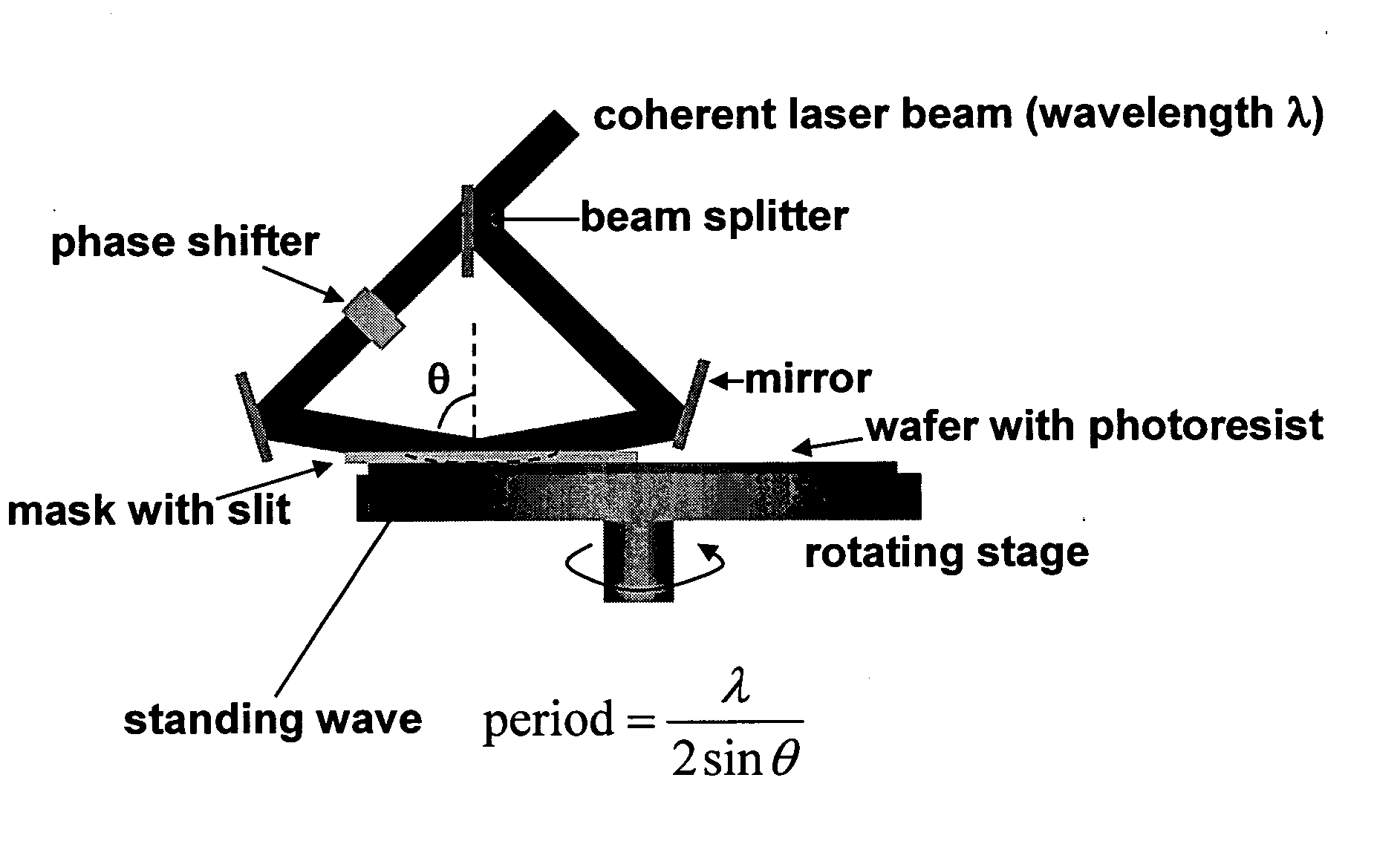
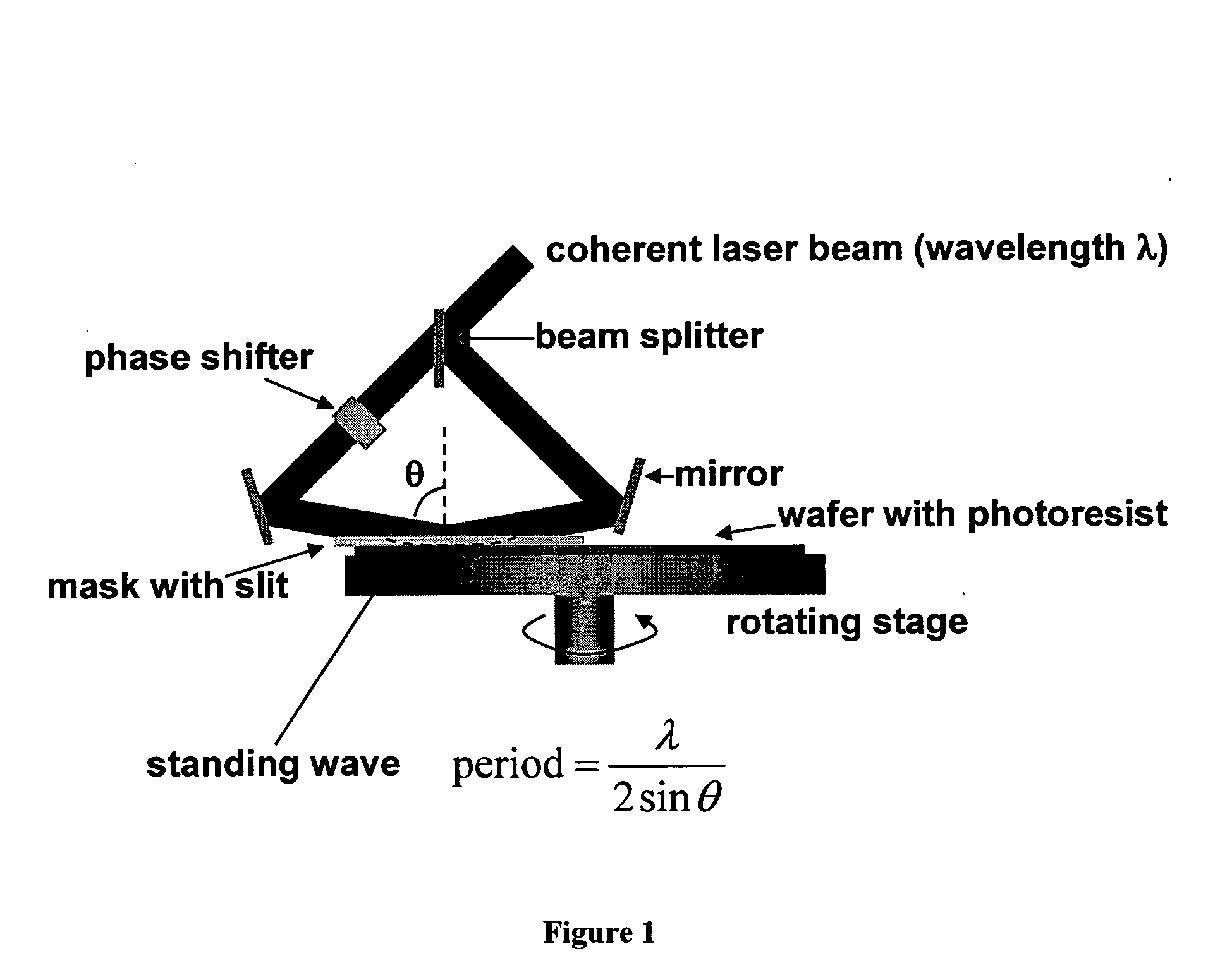
This invention differs from prior systems by allowing precise trackpitch determined by the wavelength of the laser used and the incident angle of two beams, with much better trackpitch variation than the prior systems. It can make patterns required for the master for Contact-print Servo Patterned Media (CSPM).

The method of performing RAIL and calibrating MR head geometry in self-servo writing disc drives is described in the U.S. Pat. No. 6,317,285 incorporated herein by reference.

For the master of CSPM, one preferred requirement is the trackpitch variation, and it is determined by the interference optics and not affected by the environmental disturbance significantly in the present invention.

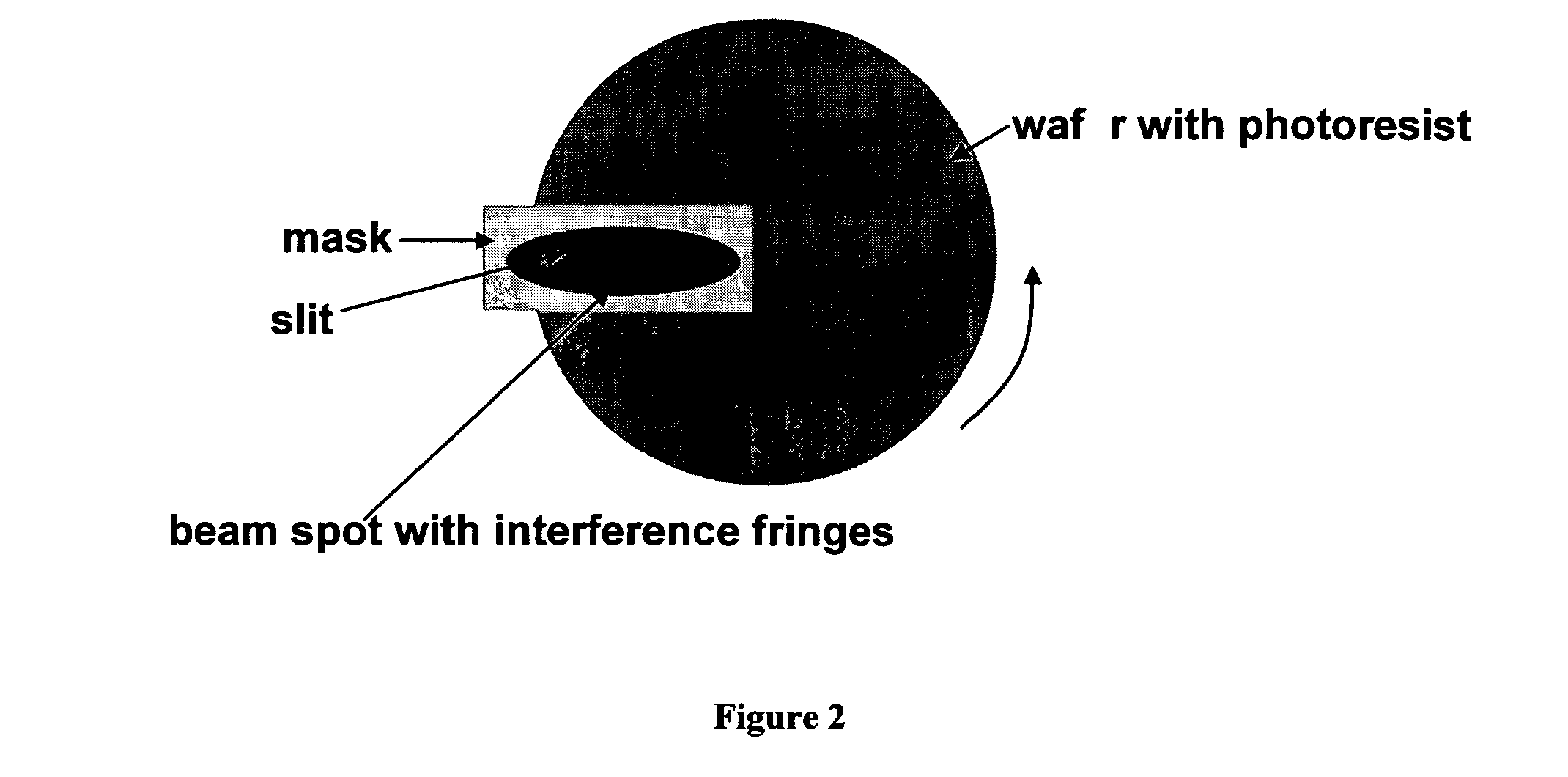
The present invention has an additional benefit of reducing the time required for recording a master, since it can be done in a single rotation of the rotating stage, as opposed to hundreds of thousands of rotations required in the prior arts using a LBR or EBR.

Briefly, the RAIL process...


PUM

PropertyMeasurementUnit
sizeaaaaaaaaaa
sizeaaaaaaaaaa
exposure timeaaaaaaaaaa

Abstract

A rotary apertured interferometric lithography (RAIL) system that includes interferometric lithography tools, a mask with a slit preferably with an arc shape, and a rotating stage is disclosed. The RAIL system could create a servo pattern of a recording-head trajectory of a hard disk drive in a master for magnetic-contact printing. The master can could be used to form arrays of sub-micron sized magnetic elements on a magnetic disk media for high-density magnetic recording applications.

Description

FIELD OF INVENTION The present invention relates to master for creating a magnetic pattern on a magnetic media. BACKGROUND Magnetic disks and disk drives are conventionally employed for storing data in magnetizable form. Preferably, one or more disks are rotated on a central axis in combination with data transducing heads positioned in close proximity to the recording surfaces of the disks and moved generally radially with respect thereto. Magnetic disks are usually housed in a magnetic disk unit in a stationary state with a magnetic head having a specific load elastically in contact with and pressed against the surface of the disk. Data are written onto and read from a rapidly rotating recording disk by means of a magnetic head transducer assembly that flies closely over the surface of the disk. Preferably, each face of each disk will have its own independent head. Disc drives at their most basic level work on the same mechanical principles as media such as compact discs or even...

Claims


Application Information

Patent Timeline
Patent Type & Authority Applications(United States)
IPC IPC(8): G03F7/00G03F7/20G03F9/00G11B5/855G11B5/86
CPCG03F7/70408G11B5/865G11B5/855
Inventor WAGO, KOICHI
Owner SEAGATE TECH LLC
Learn More