Driving force transmitting system

a transmission system and driving force technology, applied in fluid gearings, mechanical devices, gearings, etc., can solve the problems of reducing the comfort of riding, consuming a large quantity of working fluid, and delay in mechanical coupling at the clutch, so as to achieve a larger quantity of working fluid

Active Publication Date: 2005-03-24
DENSO CORP
View PDF5 Cites 44 Cited by
  • Summary
  • Abstract
  • Description
  • Claims
  • Application Information

AI Technical Summary

Benefits of technology

[0008] The present invention is made in view of the above problems, and it is an object of the present invention to provide a driving force transmitting system, which is small in size and reliable in operation. More exactly, the supply of the working fluid from oil pumps to a clutch provided between an engine and an automatic transmission device can be surely stopped, when the working fluid should not be supplied to the clutch.
[0011] Other oil circuits than the clutch, such as a lubricating device, branches off from the passage between the mechanical oil pump and the first valve means, so that the working fluid discharged from the electric oil pump is prevented by the first valve means from flowing into the other oil circuits.
[0012] Accordingly, the electric oil pump can be made smaller and the supply of the working fluid from the electric oil pump (as well as the mechanical oil pump) to the clutch can be surely prevented by the change-over means when the supply of the working fluid is not necessary.
[0013] According to another feature of the present invention, a second valve means is provided in a passage connecting the electric oil pump with the change-over means so that it allows the flow of working fluid discharged from the electric oil pump to the change-over means and it prohibits the flow of the working fluid in the reversed direction, namely from the change-over means or the mechanical oil pump to the electric oil pump. Accordingly, it can be avoided that the mechanical oil pump becomes larger in size.
[0014] According to a further feature of the present invention, the other oil circuit includes the lubricating device and a line pressure control device, which generally consume a larger quantity of the working fluid. Since the other oil circuit branches off from the passage between the mechanical oil pump and the first valve means, the working fluid discharged from the electric oil pump is prevented by the first valve means from flowing into the other oil circuit. Accordingly, the electric oil pump can be made smaller.
[0016] According to a further feature of the present invention, a control pressure generating device is provided, wherein it branches off from the passage between the first valve means and the change-over means. When the operation of the mechanical oil pump is stopped during the idling-stop of the engine, the working fluid from the electric oil pump is supplied to the control pressure generating device, so that the control of the oil pressure of the working fluid to be supplied to the clutch and the related portions of the automatic transmission device can be done even during the engine operation is stopped.

Problems solved by technology

When a clutch for an automatic transmission device is decoupled so that the automatic transmission device is disconnected from the engine during the engine operation is stopped under the idling-stop system, a delay for mechanical coupling at the clutch occurs at a re-start of the engine operation to move the vehicle.
When such a delay occurs, a shock is generated at starting the vehicle, thereby decreasing a comfortable ride.
For example, the oil circuits include a lubricating device, a device for torque converter, and so on, which generally consume a larger quantity of working fluid.
As a result, a larger size of the electric oil pump is necessary because a larger quantity of the discharged working fluid is necessary to keep the mechanical coupling at the clutch.
It is, however, disadvantageous in this prior art in the following situation.

Method used


Image

  • Driving force transmitting system
  • Driving force transmitting system

Examples


Embodiment Construction

[0019] The present invention will be explained below with reference to an embodiment.

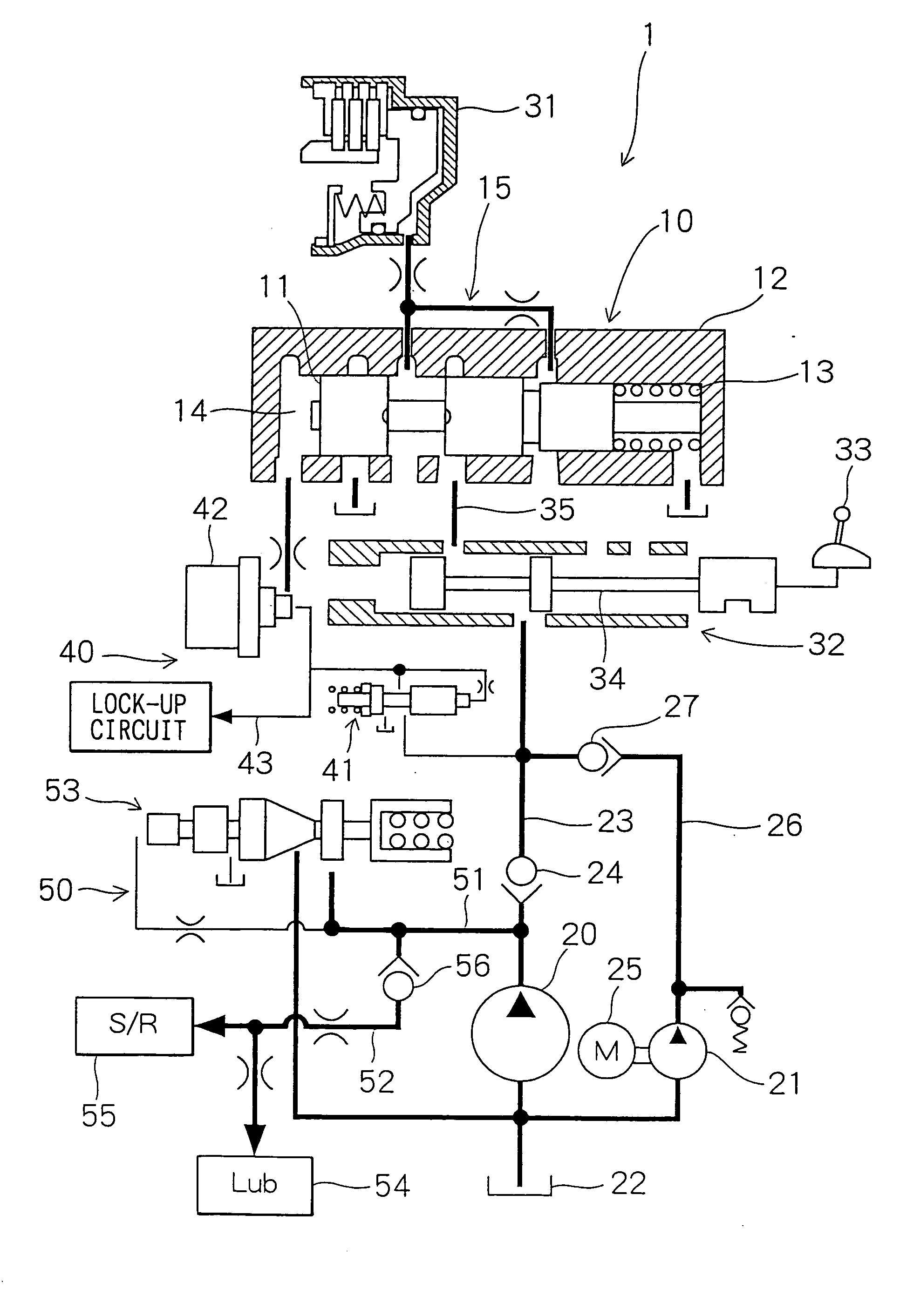
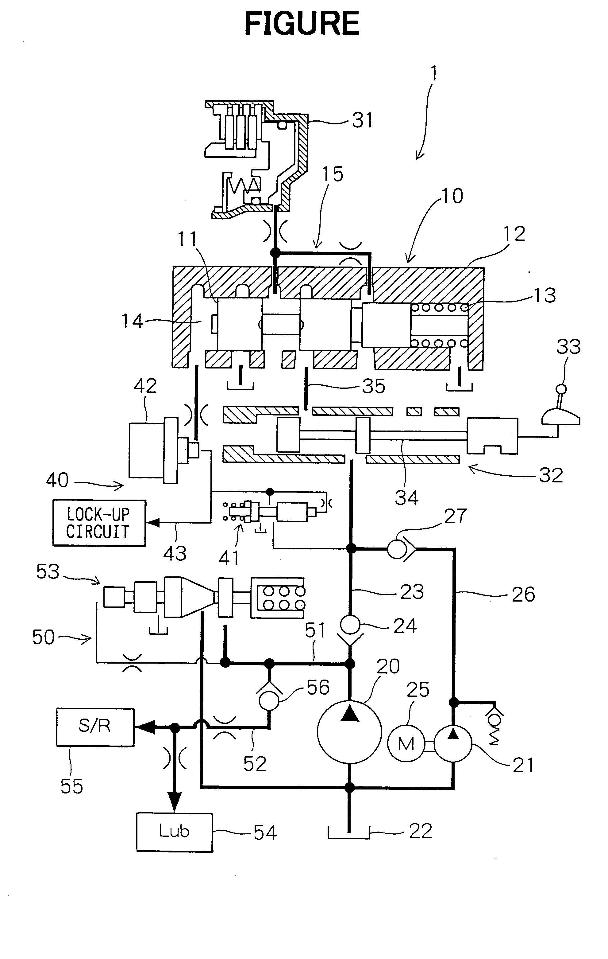
[0020] FIGURE is a schematic diagram showing a driving force transmitting system according to an embodiment of the present invention. A driving force transmitting system 1 of the invention is installed in a motor vehicle (not shown) and controls transmission of a driving force from an internal combustion engine (not shown) to an automatic transmission device (not shown). The driving force transmitting system of this invention is used in the motor vehicle, in which so-called an idling-stop system is employed. The idling-stop system is a system in which an operation of the internal combustion engine is stopped when a predetermined time period goes by after the start of the idling operation of the engine.

[0021] The driving force transmitting system 1 comprises the internal combustion engine (not shown), a torque converter (not shown), the automatic transmission device (not shown) and an oil pressure ...


PUM


Abstract

According to the present invention, a change-over means is provided between a mechanical oil pump and a clutch of an automatic transmission device for connecting an engine with the automatic transmission device, a first check valve is provided in a passage connecting the mechanical oil pump with the change-over means so that it allows the flow of working fluid discharged from the mechanical oil pump to the change-over means, and an electric oil pump is provided in parallel with the mechanical oil pump, wherein the electric oil pump is operated during an idling stop of the engine and an output side of the electric oil pump is connected to the passage between the first check valve and the change-over means so that the working fluid from the electric oil pump is supplied to the clutch of the automatic transmission device through the change-over means. Accordingly, the electric oil pump can be made smaller and the supply of the working fluid from the electric oil pump to the clutch can be surely prevented by the change-over means when the supply of the working fluid is not necessary.

Description

CROSS REFERENCE TO RELATED APPLICATION [0001] This application is based on Japanese Patent Application No. 2003-326338 filed on Sep. 18, 2003, the disclosure of which is incorporated herein by reference. FIELD OF THE INVENTION [0002] This invention relates to a driving force transmitting system, more particularly to a driving force transmitting system to be installed in a motor vehicle. BACKGROUND OF THE INVENTION [0003] A motor vehicle having an idling-stop system is under a development, wherein an engine operation is stopped to reduce carbon dioxides in exhaust gas from an internal combustion engine and to improve a fuel consumption ratio, in the case that the engine operation is in an idling operation and a time period for the idling operation exceeds a predetermined amount. When a clutch for an automatic transmission device is decoupled so that the automatic transmission device is disconnected from the engine during the engine operation is stopped under the idling-stop system, a...

Claims


Application Information

Patent Timeline
Patent Type & Authority Applications(United States)
IPC IPC(8): F16H59/08F16H61/00F16H61/02
CPCF16H61/0206F16H61/0031
Inventor TAKAGI, AKIRASUZUKI, FUMINORI
Owner DENSO CORP
Why Eureka
Try Eureka