Location and movement of remote operated vehicles

a technology of remote operated vehicles and remote control, which is applied in the direction of propulsive elements, underwater equipment, vessel construction, etc., can solve the problems of insufficient accuracy of measurements, system is less well suited to the guidance of rov system fish, and is not practical for users, so as to avoid further damage or outright loss, and facilitate the recovery of fish

Inactive Publication Date: 2005-03-31
H2EYE INT
View PDF7 Cites 15 Cited by
  • Summary
  • Abstract
  • Description
  • Claims
  • Application Information

AI Technical Summary

Benefits of technology

[0034] Advantageously, the fish further comprises a buoyancy control device operable to automatically surface the fish from a depth of water in response to one or more predetermined conditions. The predetermined conditions may include one or more of: severance of an umbilical cable; detachment of an umbilical cable from the fish; failure of a power supply operable to power the fish; and failure of thrusters operable to propel the fish. These may be regarded as “emergency” situations in which it is desirable to bring the fish to the surface quickly and automatically to avoid further damage or outright loss. Once on the surface, the GPS receiver facilitates recovery of the fish.
[0035] In one embodiment, the fish includes the position data transmitter, and the buoyancy control device is further operable to activate the GPS receiver and the position data transmitter when the fish surfaces. Thus, the fish automatically broadcasts its position, which is beneficial in situations where the umbilical cable is used for communication but is rendered unusable so that the topside cannot interrogate the fish to determine its location. Furthermore, t...

Problems solved by technology

This is of particular significance in situations where it is not possible for the user to drive the fish by using controls to steer the fish in response to images from the camera.
This may occur if, for example, the camera is damaged or the umbilical cable is severed or damaged.
However, the systems are less well suited to the guidance of ROV system fish.
The strong currents and turbulence experienced by a fish when underwater tend to contribute a large error to the INS results, making any measurements insufficiently accurate to be of use.
This is particularly the case with recreational ROV systems, in which the fish is preferably sm...

Method used


Image

  • Location and movement of remote operated vehicles
  • Location and movement of remote operated vehicles
  • Location and movement of remote operated vehicles

Examples


first embodiment

[0087] First Embodiment

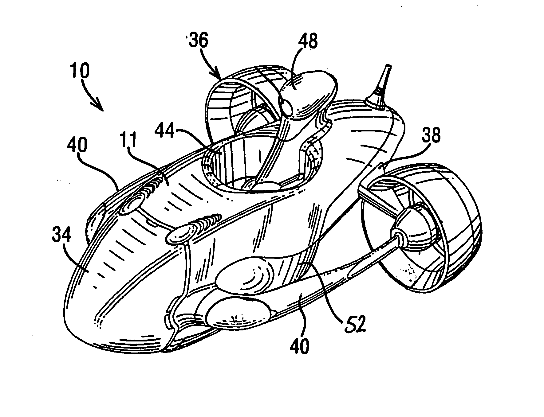
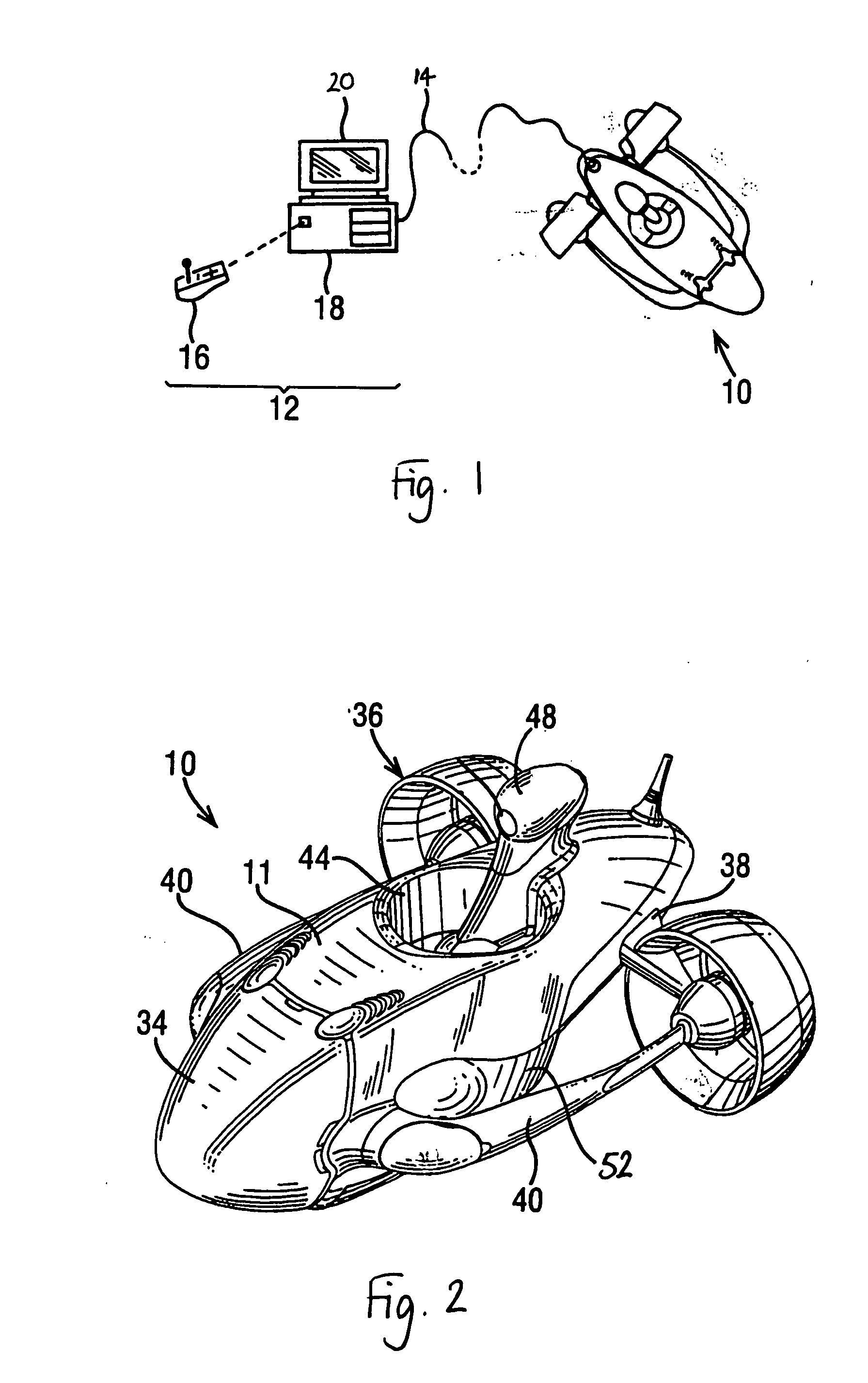
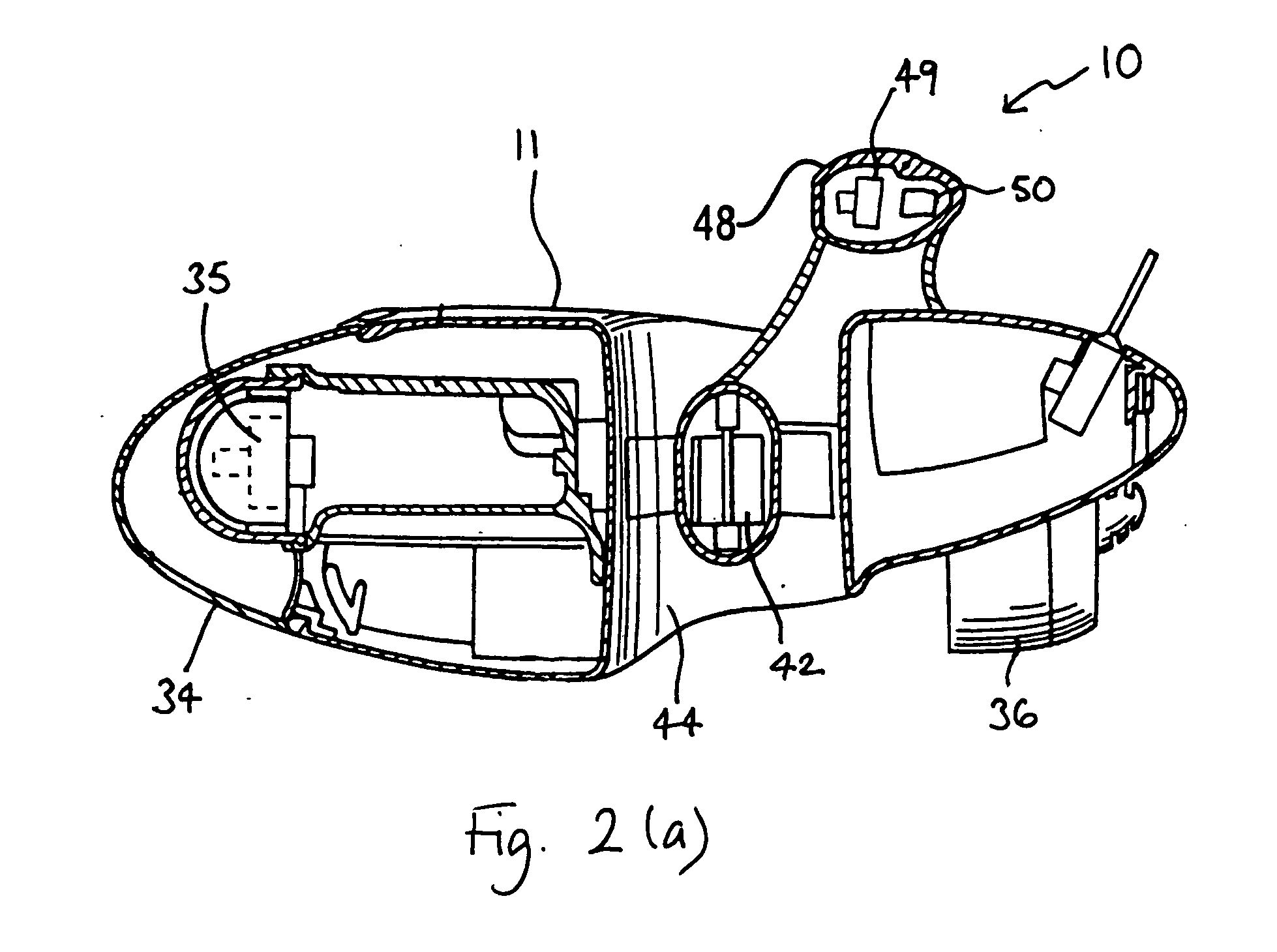
[0088] According to a first embodiment of the present invention, the ROV system described above is provided with a global positioning system (GPS) receiver mounted on or in the fish 10. By using the receiver to interrogate the GPS satellites orbiting the earth, the fish 10 is able to determine its absolute position in the known manner of using GPS. As is well-known, a typical GPS receiver does not operate accurately underwater. Thus, the GPS receiver can be used to determine the position of the fish 10 when it is on the surface of a body of water. To facilitate this, the GPS receiver is preferably mounted on the top surface of the fish 10 to ensure that it is above the water level as the fish floats on, or moves along, the surface. In the illustrated embodiment, this may conveniently be achieved by mounting the GPS receiver 50 in the periscope portion 48 of the fish 10 (see FIG. 2(a)). Alternatively, the fish 10 may be provided with any upwardly protruding por...

second embodiment

[0094] Second Embodiment

[0095] The embodiment of FIG. 3 is a configuration in which the position data is sent along the umbilical cable. However, this is not possible in the event of the cable 14 breaking, or deliberately being detached by the user, or not being used from the outset.

[0096]FIG. 4 shows an alternative embodiment in which the RF transmitter 112 in the fish 10 broadcasts to the RF receiver 108 in the topside 12 by a wireless link through air. Both transmitter 112 and receiver 108 are hence equipped with aerials 116. This wireless link allows the fish 10 to send position data to the topside 12 without using the umbilical cable 14, so that data can be communicated if the cable 14 is broken, as shown in FIG. 4. To ensure clear communication the RF transmitter 116 is preferably located on an upwardly protruding part of the fish 10, for example the periscope portion 48 shown in FIG. 2.

[0097] Although FIGS. 3 and 4 present the sending of the position data via the umbilical ...

third embodiment

[0098] Third Embodiment

[0099] Guidance of the fish can be further improved by providing a second GPS receiver in the topside.

[0100]FIG. 5 shows a block diagram of this embodiment. The same components are depicted as those in FIGS. 3 and 4, with the addition of a GPS receiver 118 in the topside computer unit 16, which is in communication with the processor 106 of the computer unit 18. Alternatively, the GPS receiver 118 can be mounted elsewhere on or in the topside, with a data link to the topside processor 106.

[0101] This embodiment allows the topside 12 to measure its absolute position by using its GPS receiver 118. The resulting measurement is supplied as position data to the topside processor 106, where it can be compared with position data supplied by the fish 10. By comparing the position data from the two units, the processor 106 can determine their relative position. The comparison may be conducted by any suitable method, such as the use of an appropriate piece of software,...


PUM


Abstract

A remote operated vehicle system comprises a topside, a fish equipped with a GPS receiver, a transmitter for transmitting GPS position data, and a receiver operable to receive the transmitted position data. Transmission may be from the fish to the topside or from the topside to the fish. Alternatively, a second transmitter and receiver give two-way transmission. These arrangements allow the position of the fish to be monitored or tracked, so that it can be readily rescued in the event of damage or breakdown. Alternatively, predetermined position data can be sent to the fish, allowing it to automatically navigate a desired route. Particular embodiments include an umbilical cable for connecting the fish and the topside together and operable to carry signals, including position data, between the two, an additional GPS receiver on the topside so that the fish can navigate to the topside unaided, and a buoyancy control device which brings the fish to the surface.

Description

BACKGROUND OF THE INVENTION [0001] The present invention relates to location and movement of remote operated vehicles of the type for use in exploration of an underwater environment. [0002] Remote operated vehicles (ROVs) of this type typically comprise an ROV system having a remote operated “submarine” unit or vehicle (a fish), a land- or ship-based remote control unit (a topside) and an umbilical cable for connecting the fish and the topside together and carrying signals between the fish and the topside. The fish may be powered by an onboard power unit or by a power unit located in the topside, in which case power is conveyed to the fish via the umbilical cable. The ROV system can be for commercial or leisure purposes. [0003] The fish is usually fitted with swimming or propulsion means, such as motor driven propellers or thrusters, which are used for maneuvering the fish underwater. Also, the fish typically carries one or more video or stills cameras. Images from the cameras can b...

Claims


Application Information

Patent Timeline
IPC IPC(8): B63C11/42
CPCB63G8/001
Inventor SHELTON, CHRIS D.
Owner H2EYE INT
Why Eureka
Try Eureka