Vacuum deposition method and vacuum deposition device

Inactive Publication Date: 2005-03-31
FUJIFILM CORP +1
View PDF2 Cites 8 Cited by
  • Summary
  • Abstract
  • Description
  • Claims
  • Application Information

AI Technical Summary

Benefits of technology

When vacuum deposition is carried out by using a vacuum deposition device, a plurality of different film forming materials may be used to carry out vacuum deposition. For example, there is known a method of forming a phosphor film of the above phosphor sheet by vacuum deposition using CsBr as a main material and EuBr2 as an activator. In the manufacture of a phosphor sheet, an extremely small amount of an activator is used as compared with a phosphor, and the control of the components of the phosphor film is important. Therefore, it is preferred to form a film on the substrate by generating vapor of

Problems solved by technology

On the other hand, when an evaporator for evaporating the main material and an evaporator for evaporating the activator are close to each other, heat generated from one evaporator interfere with heat from the other evaporator, whereby it may be difficult to control the temperature of each evaporat

Method used


Image

  • Vacuum deposition method and vacuum deposition device
  • Vacuum deposition method and vacuum deposition device
  • Vacuum deposition method and vacuum deposition device

Examples


modification 1

(Modification 1)

FIG. 5 is a plan view showing the arrangement of first evaporators and second evaporators according to Modification 1. In Modification 1, two first evaporators (Cs evaporators 311a and 311b) and two second evaporators (Eu evaporators 312a and 312b) are provided, and the four evaporators are arranged below the turntable 20 shown by a dotted line in FIG. 5 and form a rectangle. In this Modification 1, the four evaporators 311a, 311b, 312a, and 312b are installed on four points forming the rectangle. Therefore, of the distance D1 between the evaporation port of the Cs evaporator 311a and the evaporation port of the Eu evaporator 312a, the distance D2 between the evaporation port of the Cs evaporator 311a and the evaporation port of the Eu evaporator 312b, the distance D3 between the evaporation port of the Cs evaporator 311b and the evaporation port of the Eu evaporator 312a, and the distance D4 between the evaporation port of the Cs evaporator 311b and the evaporation ...

modification 2

(Modification 2)

FIG. 6 is a plan view showing the arrangement of first evaporators and second evaporators according to Modification 2. In this Modification 2, four first evaporators (Cs evaporators 311a, 311b, 311c, 311d) and four second evaporators (Eu evaporators 312a, 312b, 312c, 312d) are provided, and the eight evaporators are arranged below the turntable 20 shown by a dot line in FIG. 6 and form a rectangle. In this Modification 2, the Cs evaporators 311a, 311b, 311c, and 311d as the four first evaporators are installed on four points forming the rectangle and the Eu evaporators 312a, 312b, 312c, and 312d as the second evaporators are installed on the respective sides of the rectangle. Therefore, of the distance D1 between the evaporation port of the Cs evaporator 311a and the evaporation port of the Eu evaporator 312a, the distance D2 between the evaporation port of the Cs evaporator 311a and the evaporation port of the Eu evaporator 312d, the distance D3 between the evaporat...

modification 3

(Modification 3)

FIG. 7 is a plan view showing the arrangement of first evaporators and second evaporators according to Modification 3.

In this Modification 3, two first evaporators (Cs evaporators 311a, 311b) and four second evaporators (Eu evaporators 312a, 312b, 312c, 312d) are provided, and the six evaporators are arranged below the turntable 20 shown by a dotted line in FIG. 7. In this modification, as shown in FIG. 7, the Cs evaporator 311a is closer to the Eu evaporator 312a, and the CS evaporator 311b is closer to the Eu evaporator 312b. Therefore, of the distance DI between the evaporation port of the Cs evaporator 311a and the evaporation port of the Eu evaporator 312a and the distance D2 between the evaporation port of the Cs evaporator 311b and the evaporation port of the Eu evaporator 312b, the shortest distance becomes L2 in the expression (1).


PUM

PropertyMeasurementUnit
Lengthaaaaaaaaaa
Timeaaaaaaaaaa
Pressureaaaaaaaaaa

Abstract

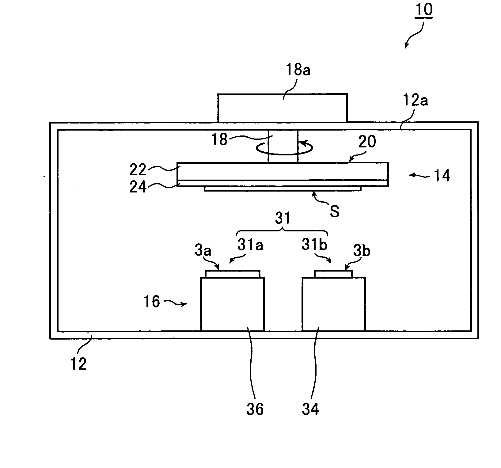
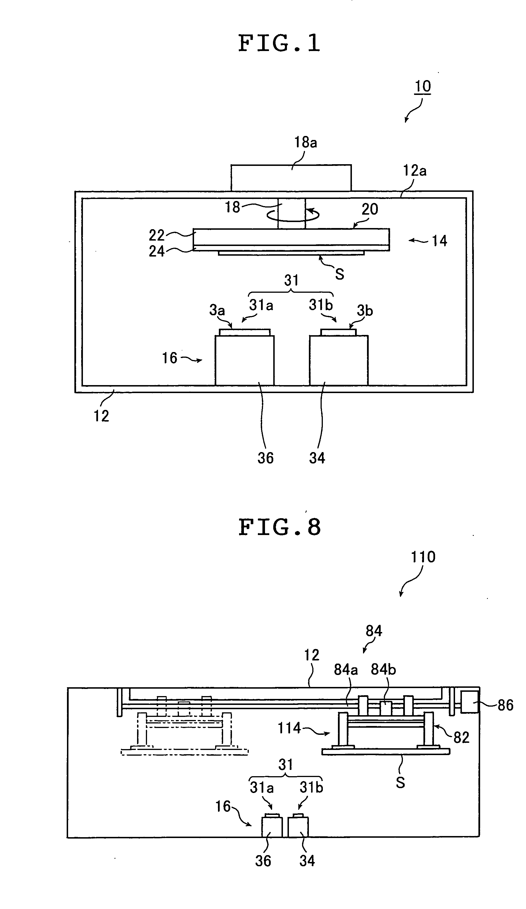
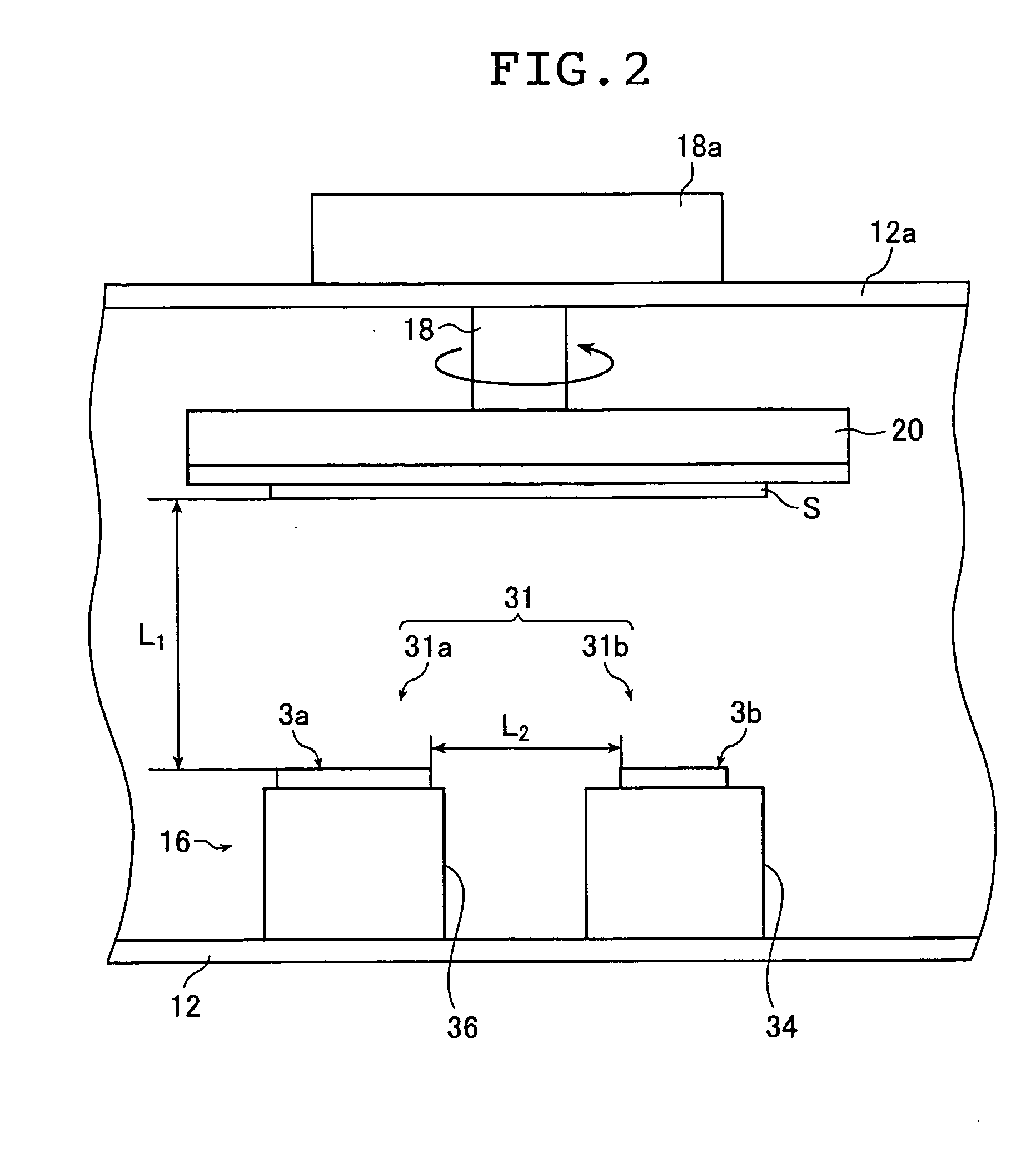
The vacuum deposition device includes a vacuum deposition chamber, a vacuum evacuator for evacuating an inside of the chamber, at least one first evaporator which evaporates a first film forming, at least one second evaporator which evaporates a second film forming material. One of the first and second evaporators which is closer to the substrate is spaced apart from the substrate in a vertical direction by 100 to 300 mm. The substrate, the first evaporator and the second evaporator are installed at positions, which satisfy a condition of an expression (1): 0.3≦L1/L2≦50. L1 is a distance in a vertical direction from a horizontal plane of a first or second evaporation port of the first or second evaporator to a surface of the substrate, and L2 is the shortest distance between the first evaporation port and the second evaporation port.

Description

BACKGROUND OF THE INVENTION The present invention relates to a vacuum deposition method and a vacuum deposition device and more specifically to a vacuum deposition method and a vacuum deposition device capable of forming a high-quality deposited film even when deposition is carried out under medium vacuum. There are known a class of phosphors which accumulate a portion of applied radiations (e.g., X-rays, α-rays, β-rays, γ-rays, electron beam, and ultraviolet radiation) and which, upon stimulation by exciting light such as visible light, give off a burst of light emission in proportion to the accumulated energy. Such phosphors called “stimulable phosphors” are employed in medical and various other applications. Known as an exemplary application is a radiation image information recording and reproducing system which employs a sheet (phosphor sheet) having a layer (to be referred to as “phosphor film” hereinafter) containing this stimulable phosphor. This phosphor sheet is called “...

Claims


Application Information

Patent Timeline
IPC IPC(8): G21K4/00C09K11/77C23C14/06C23C14/24C23C14/50C23C14/54
CPCC09K11/7733C23C14/0694C23C14/548C23C14/505C23C14/24
Inventor ISODA, YUJI
Owner FUJIFILM CORP
Why Eureka
Try Eureka