Heat insulating construction for piping and heat insulating tool kit

Inactive Publication Date: 2005-03-31
NICHIAS CORP
View PDF12 Cites 29 Cited by
  • Summary
  • Abstract
  • Description
  • Claims
  • Application Information

AI Technical Summary

Benefits of technology

[0035] The present invention provides an adiabatically heat insulating or heating heat insulating construction and a kit of elements used to form the construction. When the above-described construction is formed, since the adhesion of the heating surface of heat insulating unit to the piping is good, the heat conductivity is high, and the heat insulating unit does not overheat. Further, the folding

Problems solved by technology

Furthermore, the mounting work is troublesome because the heat insulating layer and the moistureproof layer must be wound in a spiral form.
Especially in a place where piping is entangled, it may be difficult to install the heat insulating construction (refer to Patent Document 1).
However, this heat insulating tube has no heating function, so that the pipe to be heat insulated cannot be controlled to a predetermined temper

Method used


Image

  • Heat insulating construction for piping and heat insulating tool kit
  • Heat insulating construction for piping and heat insulating tool kit
  • Heat insulating construction for piping and heat insulating tool kit

Examples


Embodiment Construction

[0060] An embodiment of the present invention will be described now in detail with reference to the accompanying drawings.

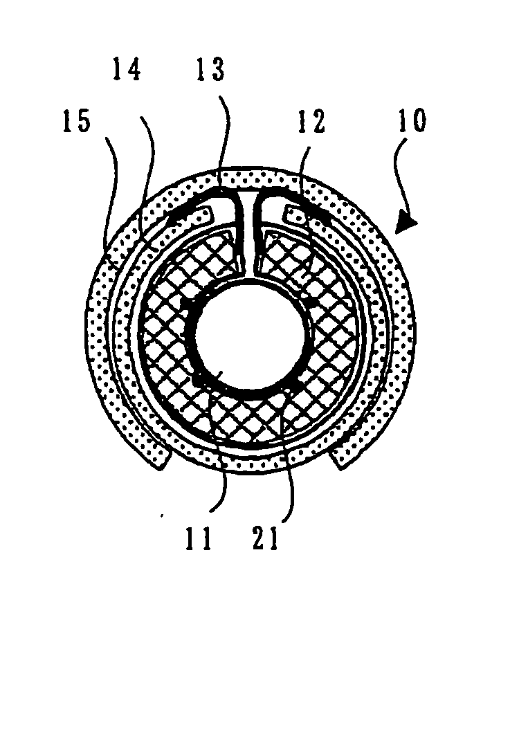
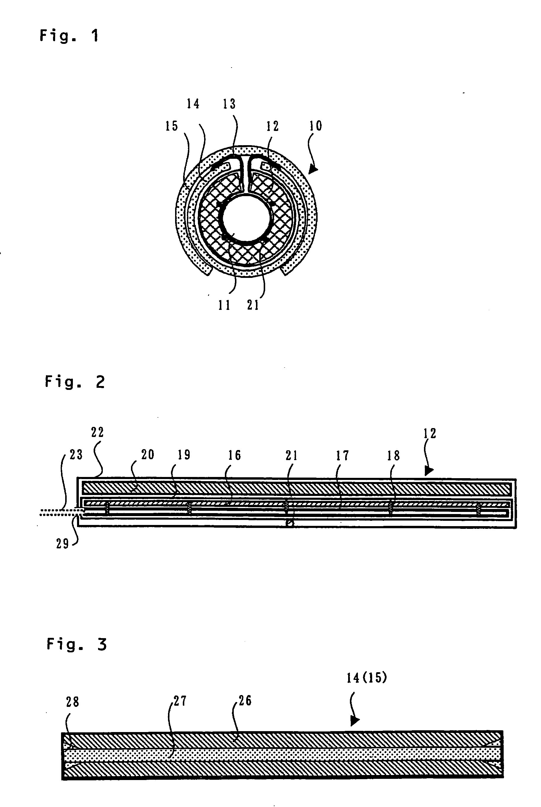
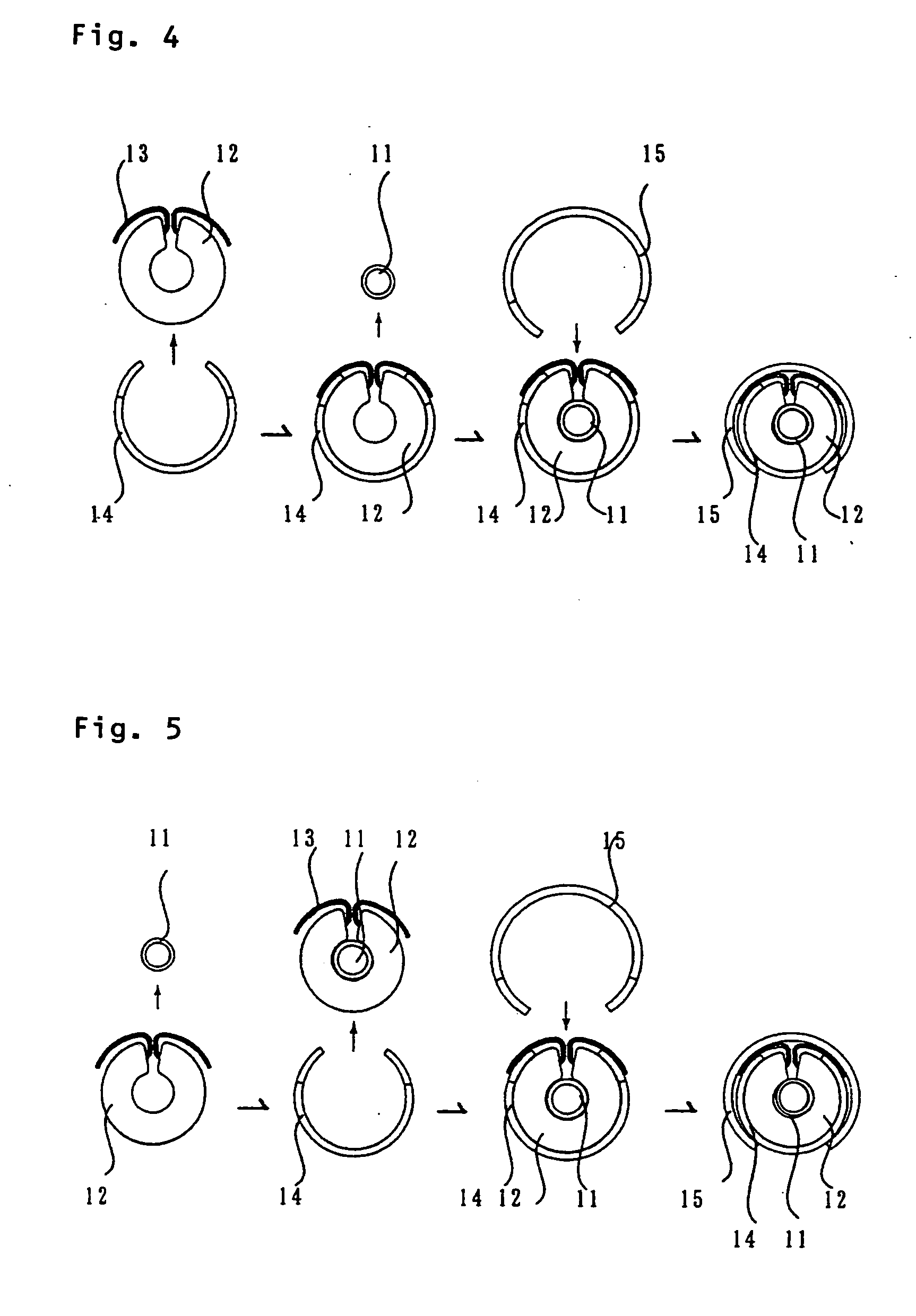
[0061]FIG. 1 is an explanatory sectional view of a heat insulating construction in which a heat insulating tool kit in accordance with the present invention including a heat insulating unit, a support cover, and an external cover is mounted on piping. FIG. 2 is an explanatory view of an example of internal configuration of a heat insulating unit. FIG. 3 is an explanatory view of a cut shape in a pipe end corner portion of a slit-shaped opening in a support cover and an external cover. FIG. 4 is an explanatory view of a procedure for mounting a heat insulating tool kit in accordance with the present invention and a heat insulating unit, a support cover, and an external cover, which are components of heat insulating construction, on piping. FIG. 5 is an explanatory view of another procedure for mounting a heat insulating tool kit in accordance with the present inv...


PUM


Abstract

There are provided a heat insulating tool kit for piping, which can easily be attached to and detached from a piping in a limited space repeatedly and fixed in a stable form, can be attached so that a heating surface is in close contact with the outer peripheral surface of piping so that heat is conducted efficiently, which results in no overheating of heated portion, can be subjected to temperature control stably, and can be used in a clean room etc. because dust particles scarcely occur, and a heat insulating construction using the heat insulating tool kit. The heat insulating tool kit includes a piping; a band-shaped heat insulating unit which includes at least a heat insulating material and preferably a heating element and is wrapped with a heat-resistant resin film; a support cover consisting of a tubular element of a C-shaped cross section having a slit-shaped opening over the total length in the axial direction of the tubular element; and preferably an external cover of almost the same shape as that of the support cover. The heat insulating construction is formed as described below. The heat insulating unit is housed so that the non-heating surface of the heat insulating unit comes into contact with the tubular element inside wall of the support cover 14, and in a state in which ear portions at both ends of a heat insulating portion are pulled out of the slit-shaped opening, the butting portion at both ends of the heat insulating portion, that is, the slit-shaped opening of support cover is pressed on the piping, by which the piping is covered with the heat insulating portion and the support cover. Next, the opening portion of external cover in a widened state is pressed on the slit-shaped opening side of the support cover, by which the heat insulating unit and the support cover are collectively covered with the external cover 15.

Description

BACKGROUND OF THE INVENTION [0001] 1. Field of the Invention [0002] The present invention relates to a heat insulating construction for piping and a heat insulating tool kit. More particularly, it relates to a heat insulating tool kit for piping, which can easily be attached to and detached from the piping in a limited space repeatedly and fixed in a stable form, can be attached so that a heating surface is in close contact with the outer peripheral surface of piping so that heat is conducted efficiently, which results in no overheating of heated portion, can be subjected to temperature control stably, and can be used in a clean room etc. because dust particles scarcely occur, and a heat insulating construction using the heat insulating tool kit. [0003] 2. Description of the Related Art [0004] Conventionally, in a manufacturing plant for semiconductors, liquid crystals, electronic components, etc., a reaction gas and a processing solution have been used in processes such as a convey...

Claims


Application Information

Patent Timeline
IPC IPC(8): F16L59/147F16L59/02F16L59/14H05B3/58
CPCF16L59/022F16L59/026Y02B30/26H05B3/565H05B3/56Y02B30/00F16L59/02F16L59/14
Inventor KOBAYASHI, TSUYOSHIMOTOYOSHI, YOSHIYUKIFUKUDA, KEIICHI
Owner NICHIAS CORP
Why Eureka
Try Eureka