Low loss RF MEMS-based phase shifter

Active Publication Date: 2005-03-31
TELEDYNE SCI & IMAGING
View PDF2 Cites 18 Cited by
  • Summary
  • Abstract
  • Description
  • Claims
  • Application Information

AI Technical Summary

Benefits of technology

[0008] Broadly, the invention provides a hybrid circuit assembly of RF MEMS switch modules and passive phase delay shifter circuits using a low loss, preferably flip-chip, interconnection technology. This hybrid circuit assembly

Problems solved by technology

However, conventional MEMS-based TTD phase shifters employ monolithic architectures that present processing compatibility, cost and packaging problems.
This not only results in lo

Method used


Image

  • Low loss RF MEMS-based phase shifter
  • Low loss RF MEMS-based phase shifter
  • Low loss RF MEMS-based phase shifter

Examples


Example

[0019] A preferred embodiment of the present invention comprises a phased array antenna phase shifter with one or more stages, each stage comprising two or more passive phase delay circuits and utilizing switched selection of the delay circuits at each stage. The phase shifter of the invention uses low loss RF MEMS switches for selecting the desired delay circuit(s) within each stage. While a preferred embodiment described in detail herein incorporates TTD switched-line phase shifter architecture, the application of this invention to other phase shifter architectures incorporating other kinds of passive elements (such as capacitors and inductors) will be apparent to those skilled in the art.

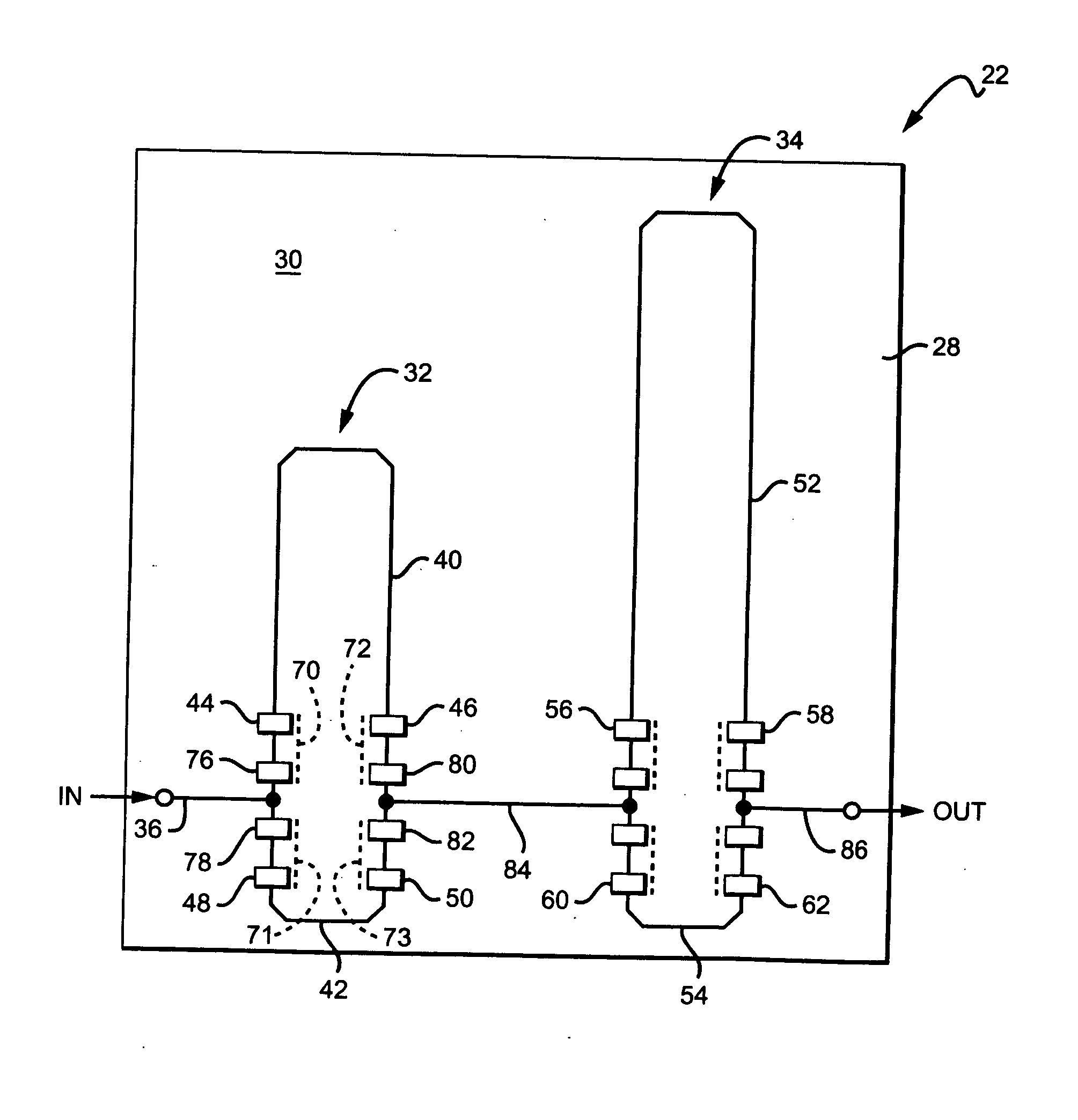
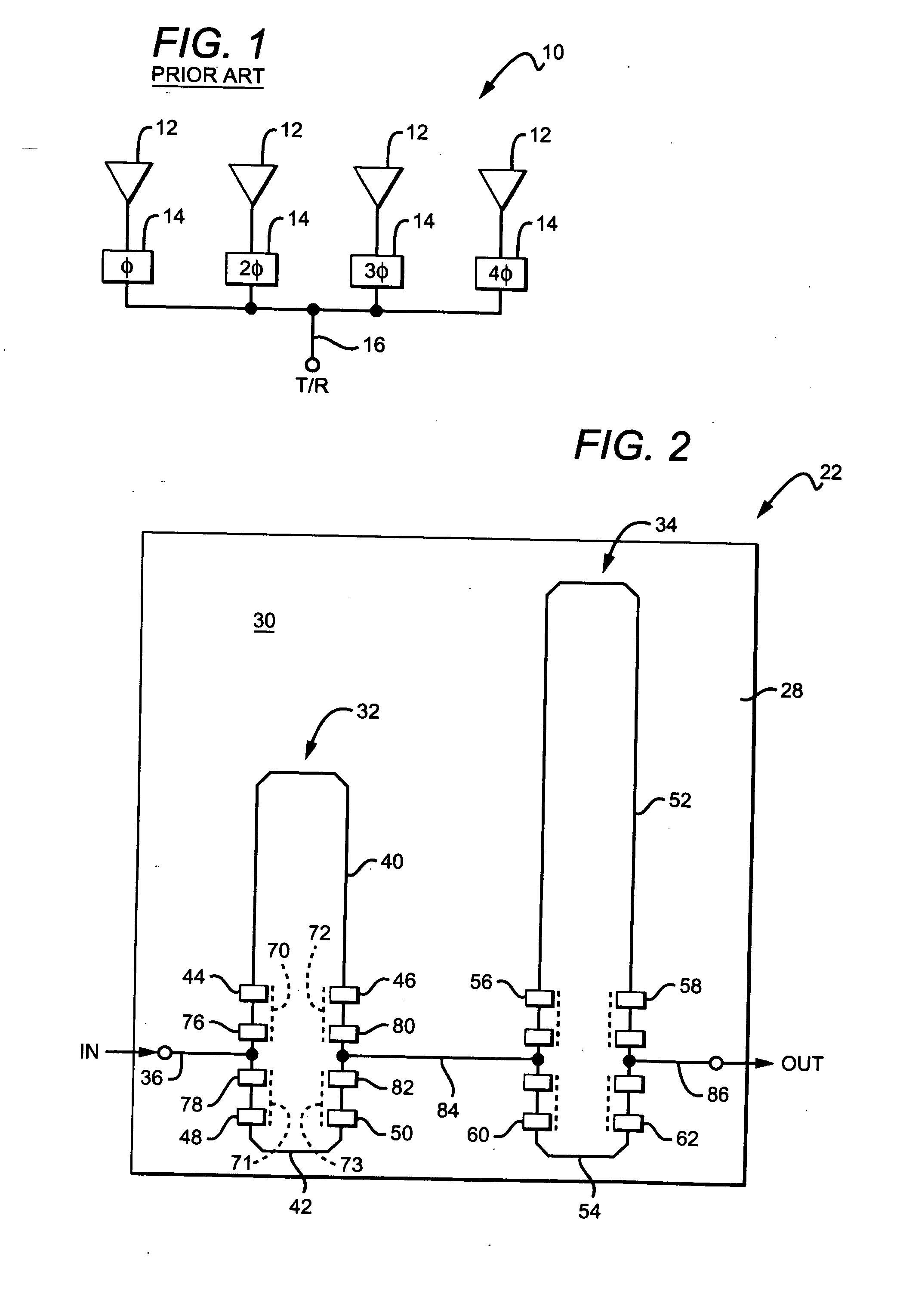
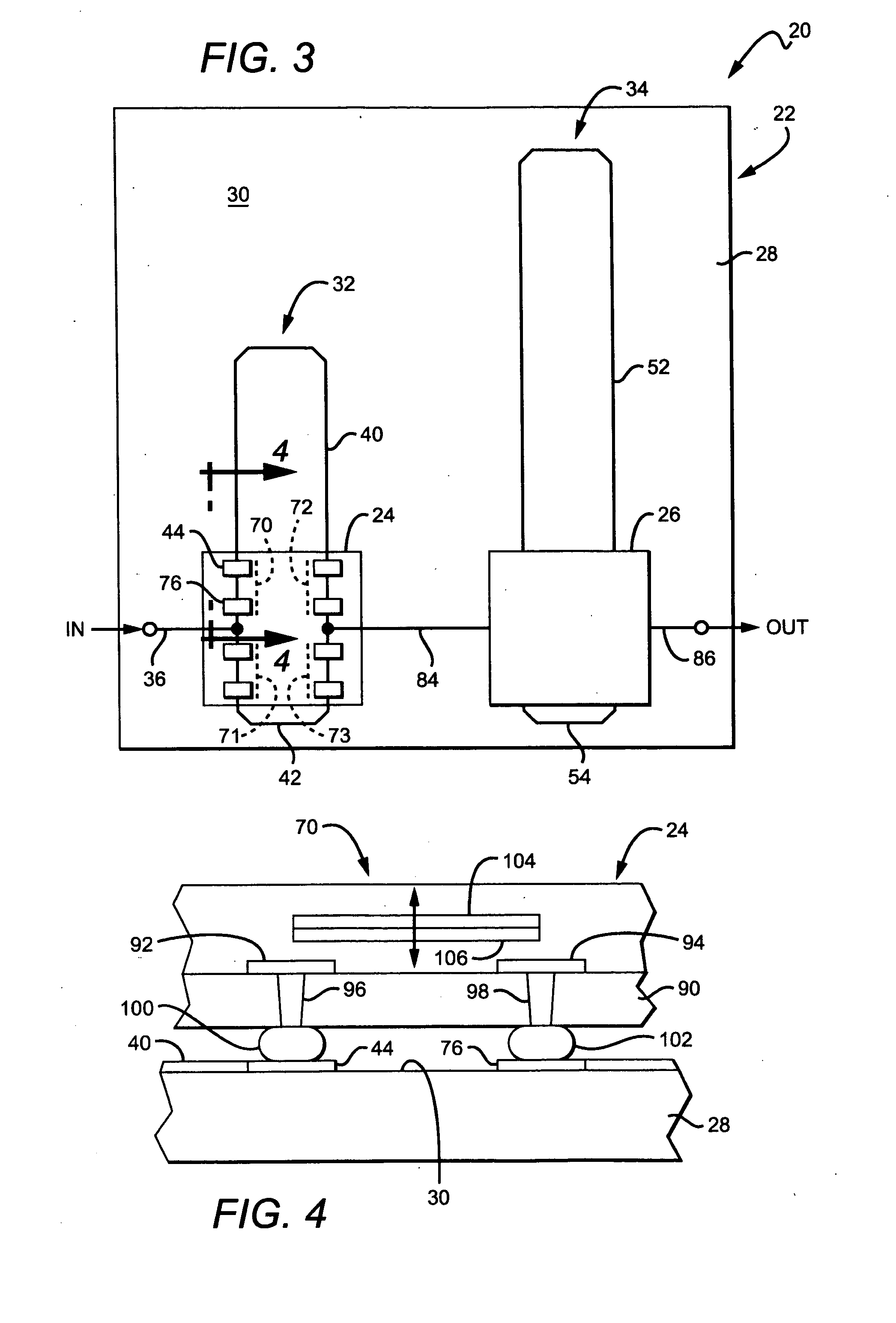
[0020] A preferred embodiment shown in FIGS. 2 and 3 comprises a hybrid phase shifter assembly 20 including a 2-bit digital delay line module 22 carrying a pair of flip-chip MEMS switch modules 24 and 26. As best seen in FIG. 2, the digital delay line module 22 comprises a base substrate 28 fabr...


PUM


Abstract

A hybrid circuit phase shifter assembly of RF MEMS switch modules and passive phase delay shifter circuits uses a low loss, preferably flip-chip, interconnection technology. The hybrid circuit assembly approach separates the fabrication of the MEMS switch modules from the fabrication of the passive phase delay circuits thereby avoiding process incompatibilities and low yields and providing substantial production cost savings. In another aspect of the invention, the integration on a common substrate of a MEMS-based hybrid circuit phase shifter assembly behind each of a plurality of radiating elements provides a compact, low cost electronic scanning antenna array.

Description

BACKGROUND OF THE INVENTION [0001] 1. Field of the Invention [0002] This invention relates generally to phase shifters utilized, for example, in electronically scanned phase array antennas, and particularly to phase shifter circuits incorporating low loss, RF microelectromechanical (MEMS) switches. [0003] 2. Description of the Related Art [0004] The beam of a multiple element or array antenna may be propagated at a predetermined angle by inserting an appropriate phase shift in the radiated signal at each element of the array. [0005]FIG. 1 is a simplified diagram of one row of a conventional phased array antenna 10 utilizing electronic beam steering, a complete planar phased array antenna having a number of such rows. The antenna 10 includes a plurality of radiating elements 12 each of which has its own phase shifter 14. An input line 16 carrying a transmission signal is coupled to each phase shifter 14, which imparts a respective predetermined phase shift to the transmission signal ...

Claims


Application Information

Patent Timeline
IPC IPC(8): H01P1/18H01Q3/26H01Q3/30
CPCH01Q3/30H01P1/184H01P1/18H01Q3/26
Inventor DENATALE, JEFFREY F.HACKER, JONATHAN B.MIHAILOVICH, ROBERT E.NORVELL, WILLIAM R.
Owner TELEDYNE SCI & IMAGING
Why Eureka
Try Eureka