Microlithographic projection exposure apparatus

Inactive Publication Date: 2005-03-31
CARL ZEISS SMT GMBH
View PDF23 Cites 235 Cited by
  • Summary
  • Abstract
  • Description
  • Claims
  • Application Information

AI Technical Summary

Benefits of technology

[0011] It is an object of the invention to specify a projection exposure apparatus designed fo

Problems solved by technology

Particularly if the terminating element is fastened to the projection lens from outside and can be removed and mounted without disassembly of the projection lens, the effo

Method used


Image

  • Microlithographic projection exposure apparatus
  • Microlithographic projection exposure apparatus
  • Microlithographic projection exposure apparatus

Examples


Embodiment Construction

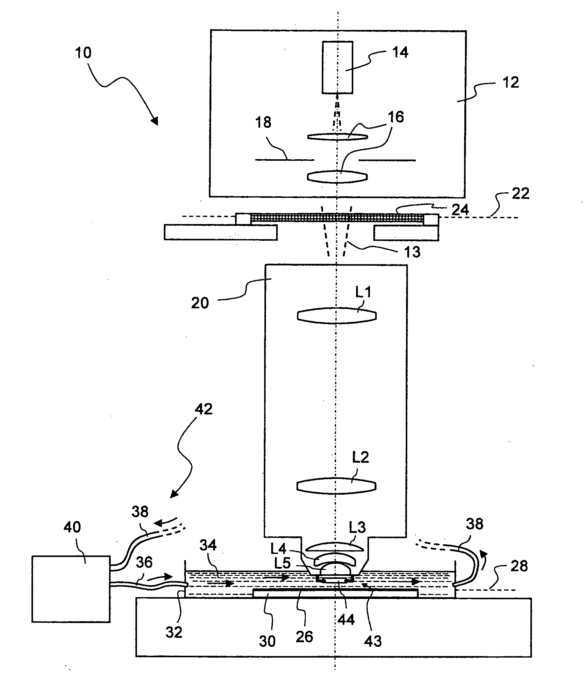
[0069]FIG. 1 shows, in greatly simplified schematic representation, a meridional section through a microlithographic projection exposure apparatus denoted overall by 10 according to a first exemplary embodiment of the invention. The projection exposure apparatus 10 exhibits an illumination system 12 for generating projection light 13, which, inter alia, comprises a light source 14, illuminating optics indicated by 16, and a diaphragm 18. In the exemplary embodiment that is represented, the projection light has a wavelength of 157 nm.

[0070] The projection exposure apparatus 10 further includes a projection lens 20 which contains a plurality of lenses, only a few of which, for the sake of clarity, are represented in exemplary manner in FIG. 1 and denoted by L1 to L5. By reason of the short wavelength of the projection light 13, the lenses L1 to L5 are fabricated from calcium-fluoride crystals, which are still sufficiently transparent even at these wavelengths. The projection lens 20 ...


PUM


Abstract

A microlithographic projection exposure apparatus contains an illumination system (12) for generating projection light (13) and a projection lens (20; 220; 320; 420; 520; 620; 720; 820; 920; 1020; 1120) with which a reticle (24) that is capable of being arranged in an object plane (22) of the projection lens can be imaged onto a light-sensitive layer (26) that is capable of being arranged in an image plane (28) of the projection lens. The projection lens is designed for immersion mode, in which a final lens element (L5; L205; L605; L705; L805; L905; L1005; L1105) of the projection lens on the image side is immersed in an immersion liquid (34; 334a; 434a; 534a). A terminating element (44; 244; 444; 544; 644; 744; 844; 944; 1044; 1144) that is transparent in respect of the projection light (13) is fastened between the final lens element on the image side and the light-sensitive layer.

Description

CROSS-REFERENCE TO RELATED APPLICATIONS [0001] This application is a continuation of International Application PCT / EP04 / 005816, with an international filing date of May 28, 2004. The full disclosure of this International Application is incorporated herein by reference.BACKGROUND OF THE INVENTION [0002] 1. Field of the Invention [0003] The present invention relates to microlithographic projection exposure apparatuses such as are used for the production of microstructured components. The invention relates, in particular, to projection exposure apparatuses with a immersion projection lens. [0004] 2. Description of Related Art [0005] Integrated electric circuits and other microstructured components are conventionally produced by several structured layers being applied onto a suitable substrate, which may be, for example, a silicon wafer. In order to structure the layers, the latter are firstly covered with a photoresist that is sensitive to light of a particular wavelength range, for ex...

Claims


Application Information

Patent Timeline
IPC IPC(8): G03F7/20
CPCG03F7/70341G03F7/70983G03F7/70833G03F7/70241G03F7/70916G03F7/70975G03F7/7015
Inventor DODOC, AURELIANSCHUSTER, KARL-HEINZMALLMANN, JORGULRICH, WILHELMROSTALSKI, HANS-JURGEN
Owner CARL ZEISS SMT GMBH
Why Eureka
Try Eureka