
Internal combustion engine controller

a technology of internal combustion engine and controller, which is applied in the direction of electric control, ignition automatic control, instruments, etc., can solve the problems of unstable idle revolving speed, technology delay in ignition timing, and incur vibration, so as to minimize the degree of combustion status variation

Inactive Publication Date: 2005-03-31
TOYOTA JIDOSHA KK
View PDF3 Cites 25 Cited by
  • Summary
  • Abstract
  • Description
  • Claims
  • Application Information

AI Technical Summary

Benefits of technology

The present invention has been made to solve the above problems and it is an object of the invention is to provide an internal combustion engine controller that is capable of minimizing the degree of combustion status variation.

Problems solved by technology

Torque variation not only makes the idle revolving speed unstable, but also incurs vibration.
If the decrement of the injection amount is lower than a limit when the injection amount is decreased, the technology delays the ignition timing.
Further, the ignition timing is delayed from the viewpoint of fuel efficiency and from the viewpoint of catalyst warm-up for exhaust emission control.
Consequently, extremely unstable combustion results.
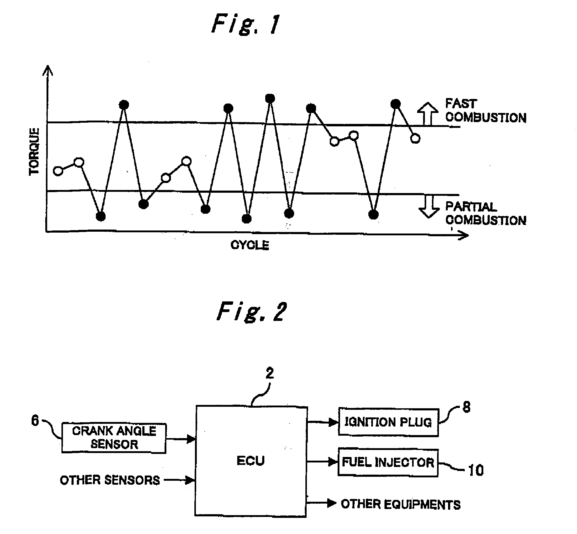
In any case, partial combustion and fast combustion alternately occur during cold fast idling, thereby incurring torque variation.
In other words, even if control is exercised according to the above conventional technology during cold fast idling, combustion status variation cannot be effectively reduced, but the degree of combustion status variation is increased.
Combustion status variation may not only incur torque variation to decrease drivability, but also degrade the exhaust gas performance.

Method used


Image

  • Internal combustion engine controller
  • Internal combustion engine controller
  • Internal combustion engine controller

Examples


first embodiment

A first embodiment of the present invention will now be described with reference to the accompanying drawings.

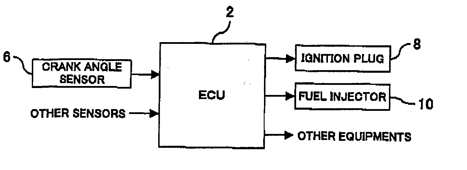
FIGS. 2 through 10 illustrates the first embodiment of an internal combustion engine controller according to the present invention. The internal combustion engine controller according to the present invention serves as an ECU (Electronic Control Unit). In accordance with output signals from a plurality of sensors, the ECU 2 exercises overall control of various equipments that concern the operating status of an internal combustion engine. As shown in FIG. 2, the input end of the ECU 2 according to the present embodiment is connected to a crank angle sensor 6. The output and of the ECU 2 is connected to an ignition plug 8 and a fuel injection valve 10. The crank angle sensor 6 is positioned near a crankshaft to output a signal to the ECU 2 at a predetermined crank angle position. The ECU 2 receives an output signal that is supplied from the crank angle sensor 6, and supplies...

second embodiment

A second embodiment of the present invention will now be described with reference to FIG. 11.

The internal combustion engine controller according to the second embodiment is implemented by causing the ECU 2 according toe the first embodiment to additionally perform a routine shown in FIG. 11.

A multicylinder engine, which has a plurality of cylinders, is generally used as an internal combustion engine for use with an automobile or other vehicle. In a multicylinder engine, all the employed cylinders usually have the same structure and are controlled in the same manner. All the cylinders are designed to generated the same torque. In reality and in many cases, however, there are stationary torque differences among the cylinders due, for instance, to differing fuel injection characteristics of injectors, nonuniform intake amounts because, for instance, of tappet clearance differences and intake interference between cylinders, combustion chamber cubic capacity differences among cylind...

third embodiment

A third embodiment of the present invention will now be described with reference to FIG. 12.

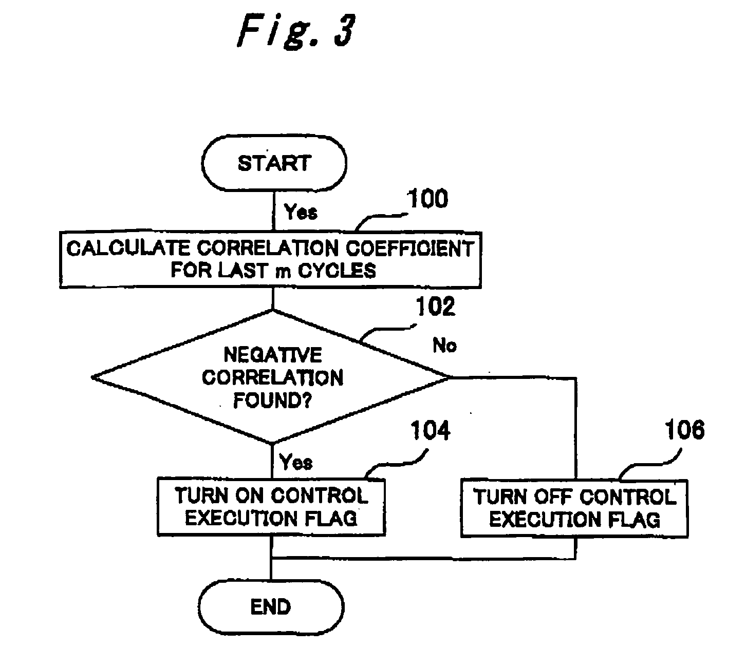
The internal combustion engine controller according to the third embodiment is implemented by causing the ECU 2 according to the first embodiment to perform a routine shown in FIG. 12 in place of the routing shown in FIG. 4.

In the first embodiment, the indicated torque is estimated from an output signal supplied from the crank angle sensor 6 and compared against predetermined judgment value T1 and T2 to check whether the combustion status of the internal combustion engine is partial combustion or not or whether it is fast combustion or not. However, the reliability of a torque value cannot easily be assured due, for instance, to friction torque variation, aging, and crank angle sensor signal accuracy. Therefore, if the employed threshold values (judgment values T1 and T2) are the magnitude of torque values as mentioned above erroneous judgments may be formed depending on the reliability ...


PUM


Abstract

If the combustion status detected in a steady state (e.g., during cold fast idling) is partial combustion, the setting of a combustion status control parameter (e.g., ignition timing control parameter) for the next cycle is adjusted so as to provide an increased degree of partial combustion (e.g., by adjusting the ignition timing control parameter for the delay side). If, on the other hand, the detected combustion status is fast combustion, the setting of the control parameter for the next cycle is adjusted so as to provide an increased degree of fast combustion (e.g., by adjusting the ignition timing control parameter for the advance side). The combustion status can be detected in accordance with an output parameter that correlates with the engine torque.

Description

BACKGROUND OF THE INVENTION 1. Field of the Invention The present invention relates to internal combustion engine control technologies, and more particularly to an internal combustion engine control technology suitable for minimizing the degree of combustion status variation during idling. 2. Background Art While an internal combustion engine is idle, combustion status varies from one cylinder to another. Therefore, torque variation is likely to occur in the internal combustion engine. Torque variation not only makes the idle revolving speed unstable, but also incurs vibration. A known technology disclosed, for instance, by Japanese Patent No. 2505304 (hereinafter referred to as “Patent Document 1”) is used to minimize the degree of torque variation during idling. The technology disclosed by Patent Document 1 detects the revolution variation of each cylinder during idling. If the magnitude of the revolution variation of a certain cylinder exceeds an upper limit, this technology...

Claims


Application Information

Patent Timeline
Patent Type & Authority Applications(United States)
IPC IPC(8): F02P5/15F02D13/02F02D37/02F02D41/00F02D41/02F02D41/04F02D43/00F02D45/00
CPCF02D37/02F02D41/0255Y02T10/26Y02T10/46F02P5/1506Y02T10/12Y02T10/40
Inventor UEDA, KOICHIKUROKI, RENTAROYOSHIDA, SHOZO
Owner TOYOTA JIDOSHA KK
Learn More