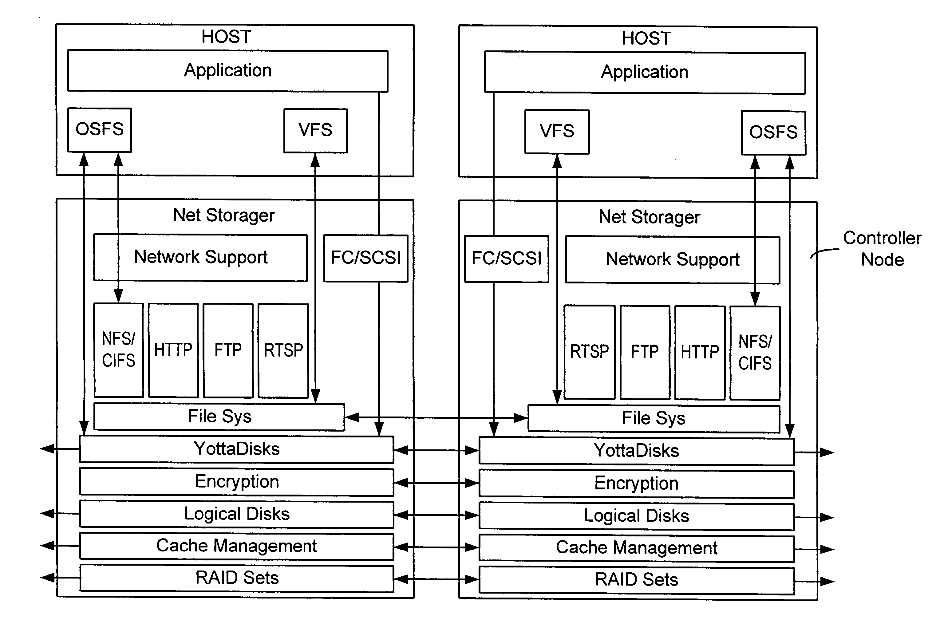
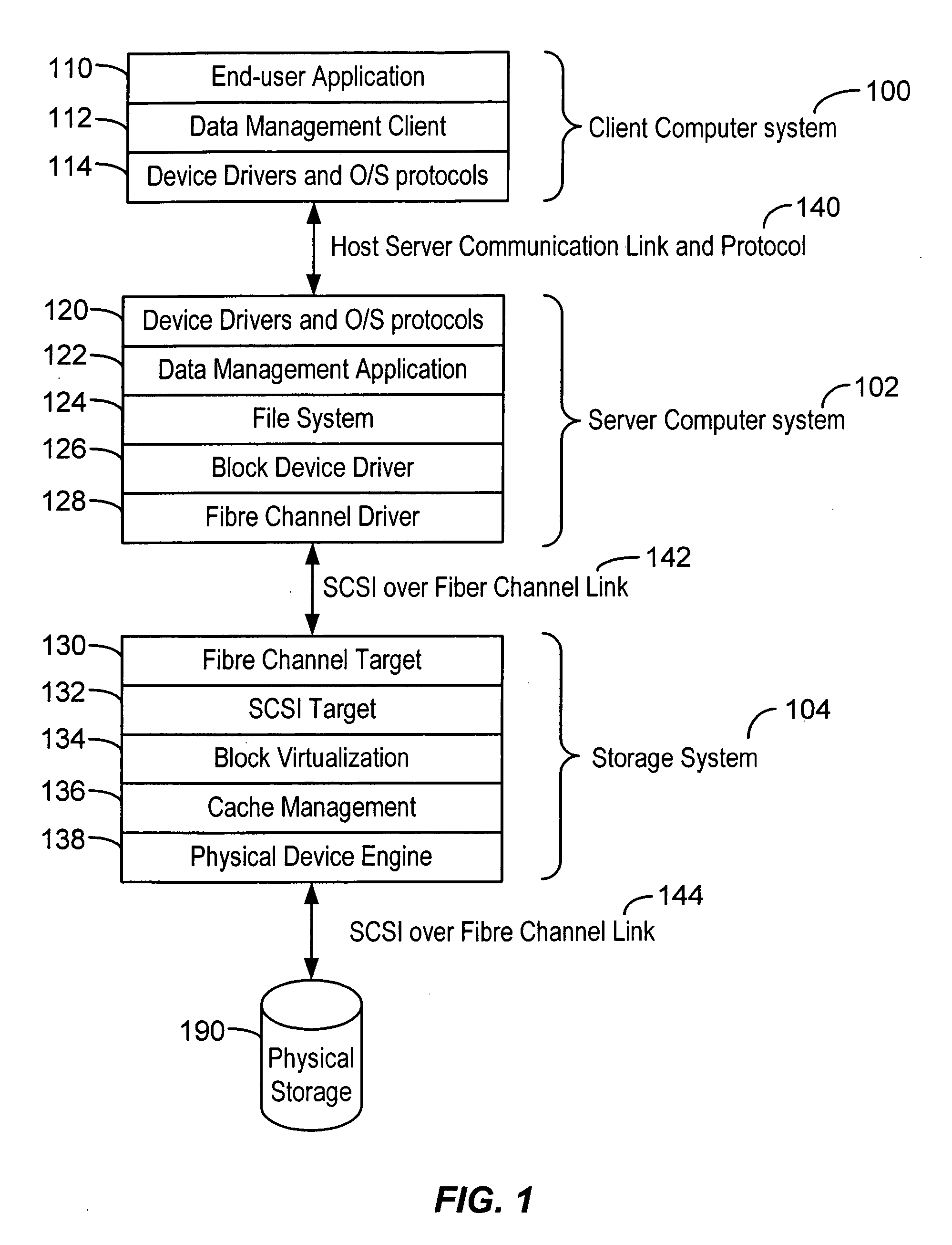
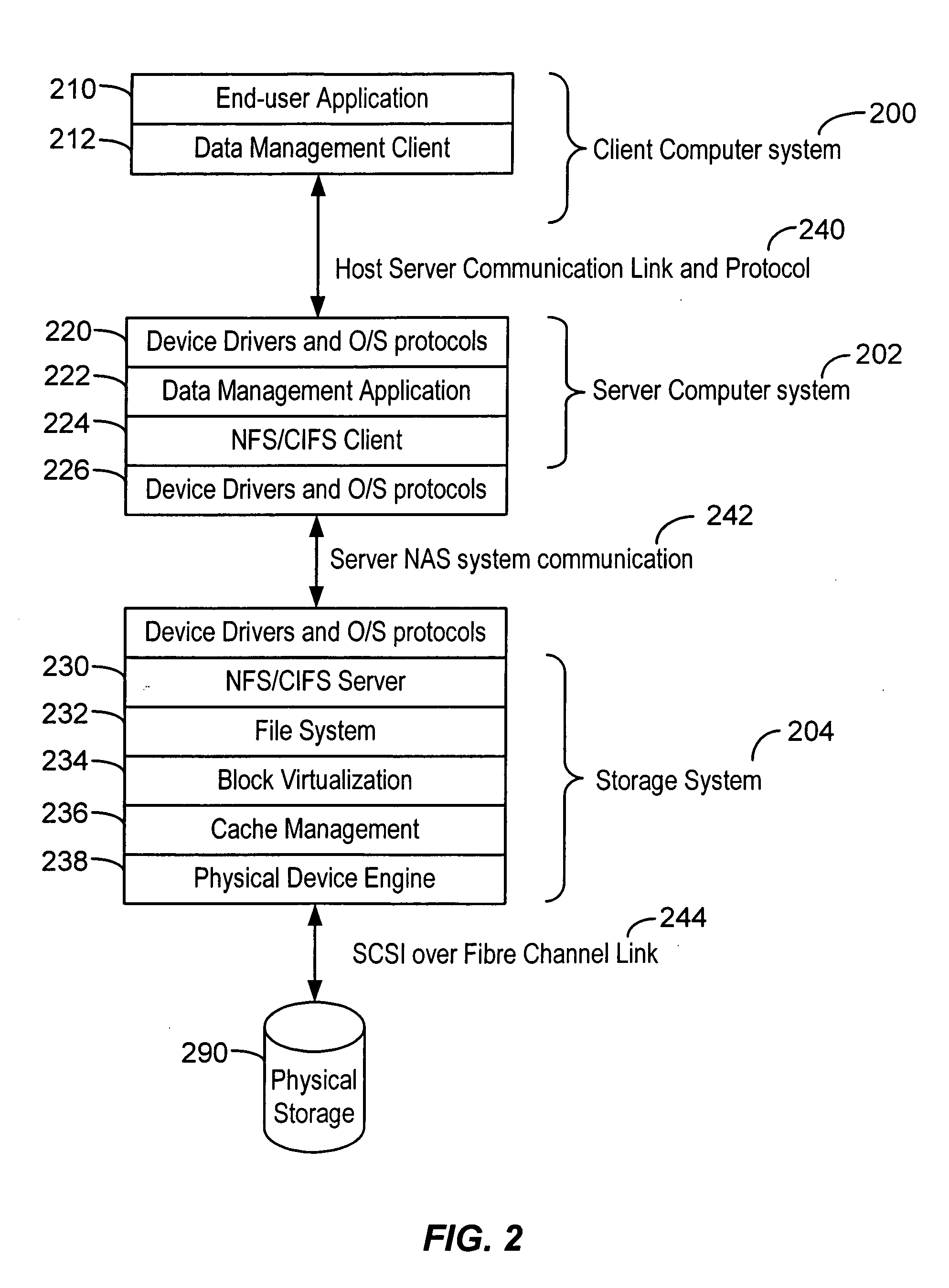
[0005] According to the present invention, a server is embedded directly into a storage subsystem. When moving between the storage subsystem domain and the server domain, data
copying is minimized.
Data management functionality written for traditional servers may be implemented within a stand-alone storage subsystem, generally without
software changes to the ported subsystems. The hardware executing the storage subsystem and server subsystem are implemented in a way that provides reduced or negligible latency, compared to traditional architectures, when communicating between the storage subsystem and the server subsystem. In one aspect, a plurality of clustered controllers are used. In this aspect, traditional load-balancing software can be used to provide
scalability of server functions. One end-result is a storage
system that provides a wide range of
data management functionality, that supports a heterogeneous collection of clients, that can be quickly customized for specific applications, that easily leverages existing
third party software, and that provides optimal performance.
[0006] According to an aspect of the invention, a method is provided for embedding functionality normally present in a server computer system into a storage system. The method typically includes providing a storage system having a first processor and a second processor coupled to the first processor by an interconnect medium, wherein processes for controlling the storage system execute on the first processor,
porting an
operating system normally found on a
server system to the second processor, and modifying the
operating system to allow for low latency communications between the first and second processors.
[0007] According to another aspect of the invention, a storage system is provided that typically includes a first processor configured to control storage functionality, a second processor, an interconnect medium communicably
coupling the first and second processors, an
operating system ported to the second processor, wherein said operating system is normally found on a
server system, and wherein the operating system is modified to allow low latency communication between the first and second processors.
[0008] According to yet another aspect of the invention, a method is provided for optimizing communication performance between server and storage system functionality in a storage system. The method typically includes providing a storage system having a first processor and a second processor coupled to the first processor by an interconnect medium,
porting an operating system normally found on a
server system to the second processor, modifying the operating system to allow for low latency communications between the first and second processors, and
porting one or more
file system and data management applications normally resident on a server system to the second processor.
[0009] According to still another aspect of the invention, a method is provided for implementing clustered embedded server functionality in a storage system controlled by a plurality of storage controllers. The method typically includes providing a plurality of storage controllers, each storage controller having a first processor and a second processor communicably coupled to the first processor by a first interconnect medium, wherein for each storage controller, an operating system normally found on a server system is ported to the second processor, wherein said operating system is allows low latency communications between the first and second processors. The method also typically includes providing a second interconnect medium between each of said plurality of storage controllers. The second communication medium may
handle all inter-processor communications. A third interconnect medium is provided in some aspects, wherein inter-processor communications between the first processors occur over one of the second and third mediums and inter-processor communications between the second processors occur over the other one of the second and third mediums.
[0010] According to another aspect of the invention, a storage system is provided that implements clustered embedded server functionality using a plurality of storage controllers. The system typically includes a plurality of storage controllers, each storage controller having a first processor and a second processor communicably coupled to the first processor by a first interconnect medium, wherein for each storage controller, processes for controlling the storage system execute on the first processor, an operating system normally found on a server system is ported to the second processor, wherein said operating system is allows low latency communications between the first and second processors, and one or more file system and data management applications normally resident on a server system are ported to the second processor. The system also typically includes a second interconnect medium between each of said plurality of storage controllers, wherein said second interconnect medium handles inter-processor communications between the controller cards. A third interconnect medium is provided in some aspects, wherein inter-processor communications between the first processors occur over one of the second and third mediums and inter-processor communications between the second processors occur over the other one of the second and third mediums.


