Thermal power process

Inactive Publication Date: 2005-04-07
ALSTOM TECH LTD
View PDF19 Cites 64 Cited by
  • Summary
  • Abstract
  • Description
  • Claims
  • Application Information

AI Technical Summary

Benefits of technology

[0020] An exemplary embodiment of a thermal power unit for realizing the process in accordance with principles of the present invention is a gas turbo group with a closed cycle and in which downstream from a last turbine at least one waste heat steam generator is arranged as a first heat sink. Also downstream from it one or several additional heat sinks are arranged in which steam contained in the process fluid is condensed and separated. A boiler feed pump transports the resulting condensate into the waste heat steam generator where an optionally overheated amount of steam or a saturated steam is generated. The generated steam is returned to the performance fluid on the high-pressure side of the closed gas turbine, expanded, cooled and condensed in the turbine. To this extent such a machine is similar to a conventional STIG machine that is known per se. Nonetheless known STIG machines work in an open cycle and have a correspondingly large water consumption rate. The closed gas turbine in accordance with the invention recirculates the water. This can be accomplished easily within the low pressure part of the thermal power unit is operated under hyperbaric pressure. Already above the ambient temperature a main part of the contained steam is separated from the gas cycle. The pressure in the low-pressure part of the thermal power unit, i.e. during the fourth and first thermodynamic state, ranges above 5 bar, for example at 10 bar, in an exemplary embodiment. Low pressure in the range between 5 and 10 bar proves to be especially advantageous with regard to the condensation temperatures, the performance density and the required dimensions of the components. The smaller s

Problems solved by technology

This, taking the given limitations of the upper process temperature into account, is not possible by increasing the specific enthalpy of the compressed process gas but rather by adding another enthalpy stream in the form of a medium that is heated by the process waste heat.
This does not provide perfect theoretical

Method used


Image

  • Thermal power process
  • Thermal power process
  • Thermal power process

Examples


Embodiment Construction

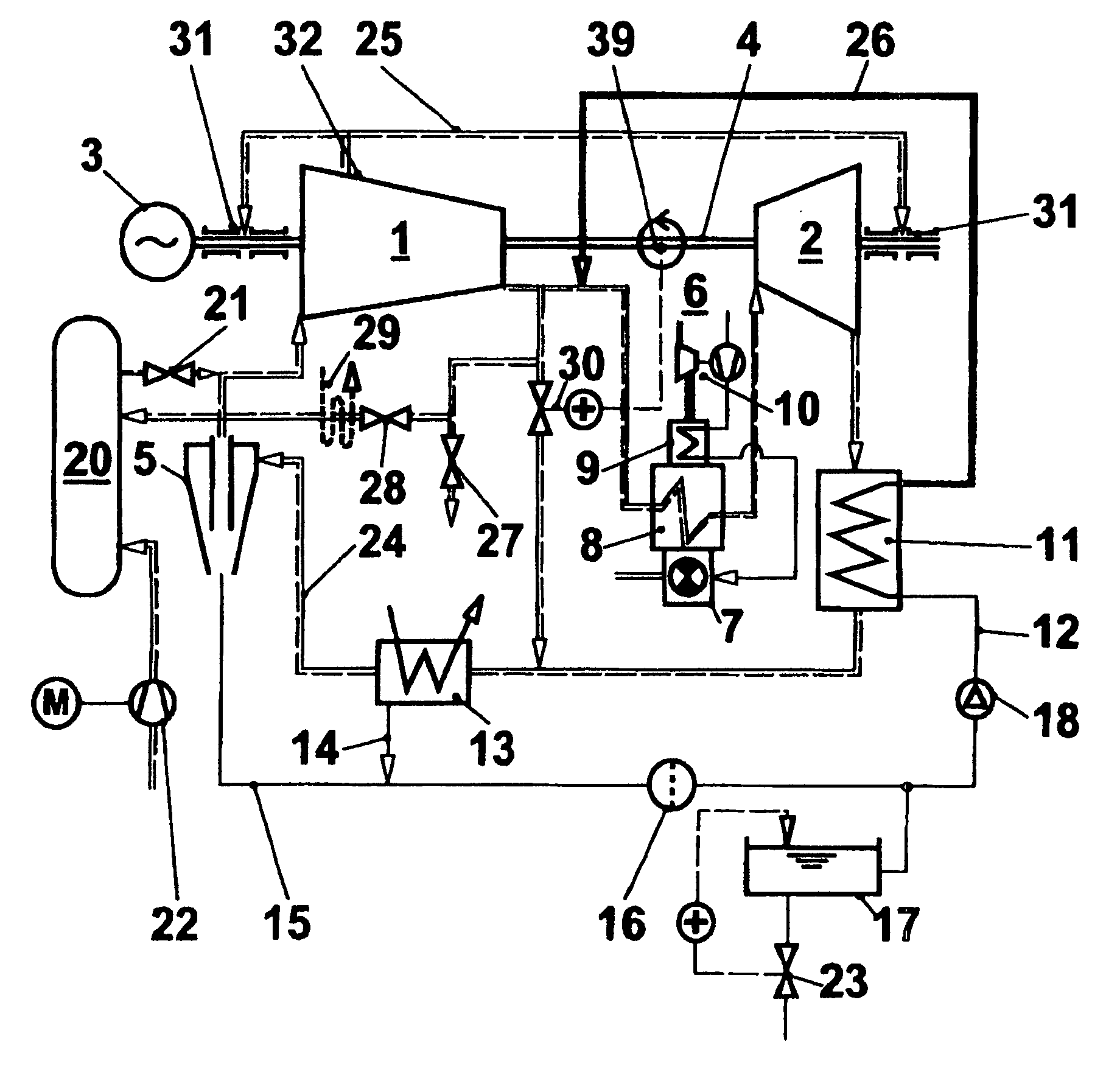
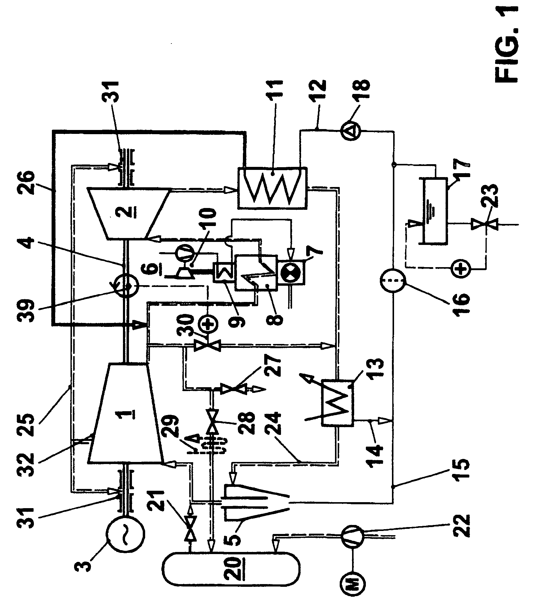
[0025]FIG. 1 shows a first embodiment of a power generation unit that operates based on the thermal power process in accordance with the invention. The embodiment that is shown is based on a closed gasturbo group. A compressor 1, a turbine 2, and a sink 3 are arranged on a mutual shaft 4. The compressor 1 as compression means compresses a gaseous primary process fluid, in the most simple form air, in a closed process to an upper process pressure. It is also possible to compress any other gas. For example, helium cycles provide advantages and have been realized for quite some time. Since it is a closed system, the starting pressure of the process fluid can clearly deviate up or down from the ambient pressure and above all can be a multiple of the ambient pressure. The compressed process fluid flows through means for supplying heat, especially a heat transfer medium, heat exchanger 6, on the secondary side. On the primary side it is connected to a charged combustion medium. A compress...


PUM


Abstract

In a power generation unit, especially in a gasturbo group, a gaseous process fluid is guided in a closed cycle. The gaseous process fluid flows through a compression device (1), a heater (6) and an expansion device (2), especially a turbine. Downstream from the expansion device at least one heat sink (11, 13) is arranged in which the gaseous process fluid is cooled before it is returned to the compressor device (1). At least one heat sink includes a waste heat steam generator in which an overheated amount of steam (26) is generated that is added to the compressed gaseous process fluid. Together with the gaseous process fluid the steam flows through the heater (6) if necessary and is expanded together with it. The expanded steam condenses in the waste heat steam generator (11) and another heat sink (13); the condensate is processed in a filter (16) and is returned to the waste heat steam generator (11) under pressure via a feed pump (18). Due to the closed process any kind of process fluid and process filling for controlling performance can be used.

Description

[0001] This application is a Continuation of, and claims priority under 35 U.S.C. § 120 to, International application number PCT / EP03 / 50053, filed 11 Mar. 2003, and claims priority under 35 U.S.C. § 119 to Swiss application number 2002 0443 / 02, filed 14 Mar. 2002, the entireties of both of which are incorporated by reference herein. BACKGROUND OF THE INVENTION [0002] 1. Field of the Invention [0003] The present invention concerns a thermal power process. It furthermore concerns a device suitable for carrying out a cyclic process as well as a power generation unit that utilizes the device based on the process of the invention. [0004] 2. Brief Description of the Related Art [0005] Power generation units with closed processes are known per se in the state of the art. Examples are the two-phase steam turbine processes. Also known and often technically realized are processes in which a gaseous performance fluid initially is compressed, heated and then expanded in an engine accompanied by...

Claims


Application Information

Patent Timeline
IPC IPC(8): F01K21/04
CPCF01K21/04
Inventor FRUTSCHI, HANS ULRICH
Owner ALSTOM TECH LTD
Why Eureka
Try Eureka