Cooling system with refrigerant for air conditioning and lowering temperature of engine

a technology of engine cooling and refrigerant, which is applied in the direction of machines/engines, combustion air/fuel air treatment, light and heating apparatus, etc., can solve the problems of short life span, excessively high engine system temperature, and long period of engine running fiercely, etc., to prolong the length of the cooling system, increase the contact area, and enhance the effect of engine efficiency

Inactive Publication Date: 2005-04-07
LIN TZU TANG
View PDF4 Cites 14 Cited by
  • Summary
  • Abstract
  • Description
  • Claims
  • Application Information

AI Technical Summary

Benefits of technology

[0007] Another embodiment of the present invention provides that the intake pipe covered by the heat exchanger is replaced with the oil pipeline and the oil pipeline in the heat exchanger has smaller pipe diameter with a roundabout way so as to extend the length thereof in the heat exchanger as long as possible for increasing con

Problems solved by technology

These traditional cooling systems for engine are designed to meet ordinary air temperature condition and driving requirement so that it is incapable of treating abnormally high air temperature si

Method used


Image

  • Cooling system with refrigerant for air conditioning and lowering temperature of engine
  • Cooling system with refrigerant for air conditioning and lowering temperature of engine
  • Cooling system with refrigerant for air conditioning and lowering temperature of engine

Examples


Embodiment Construction

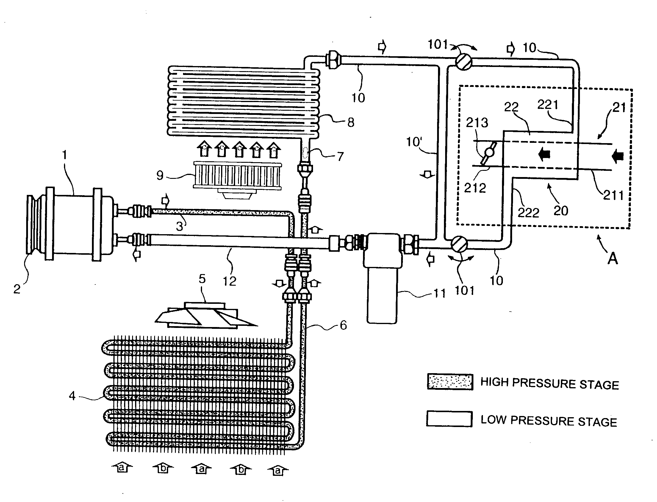
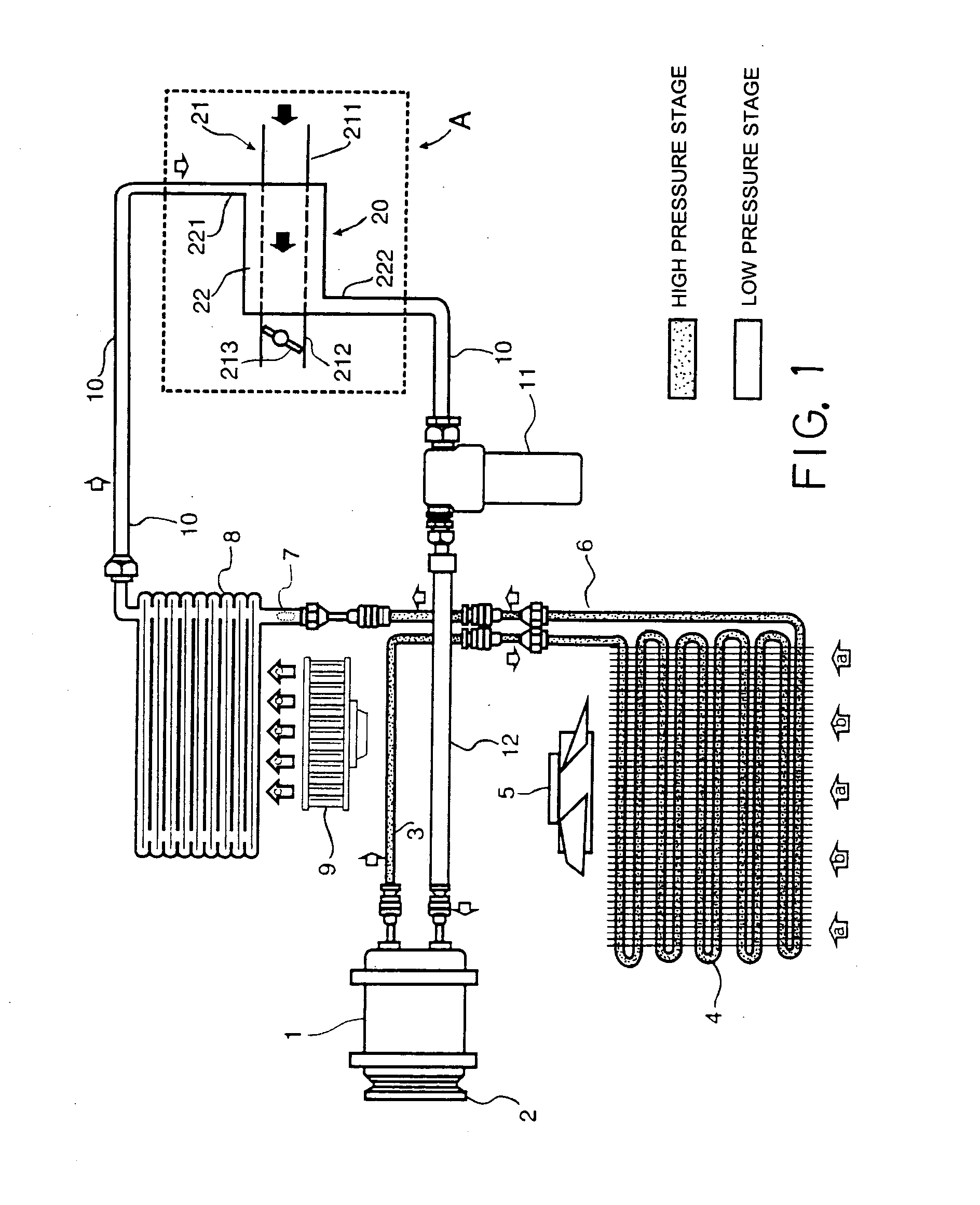
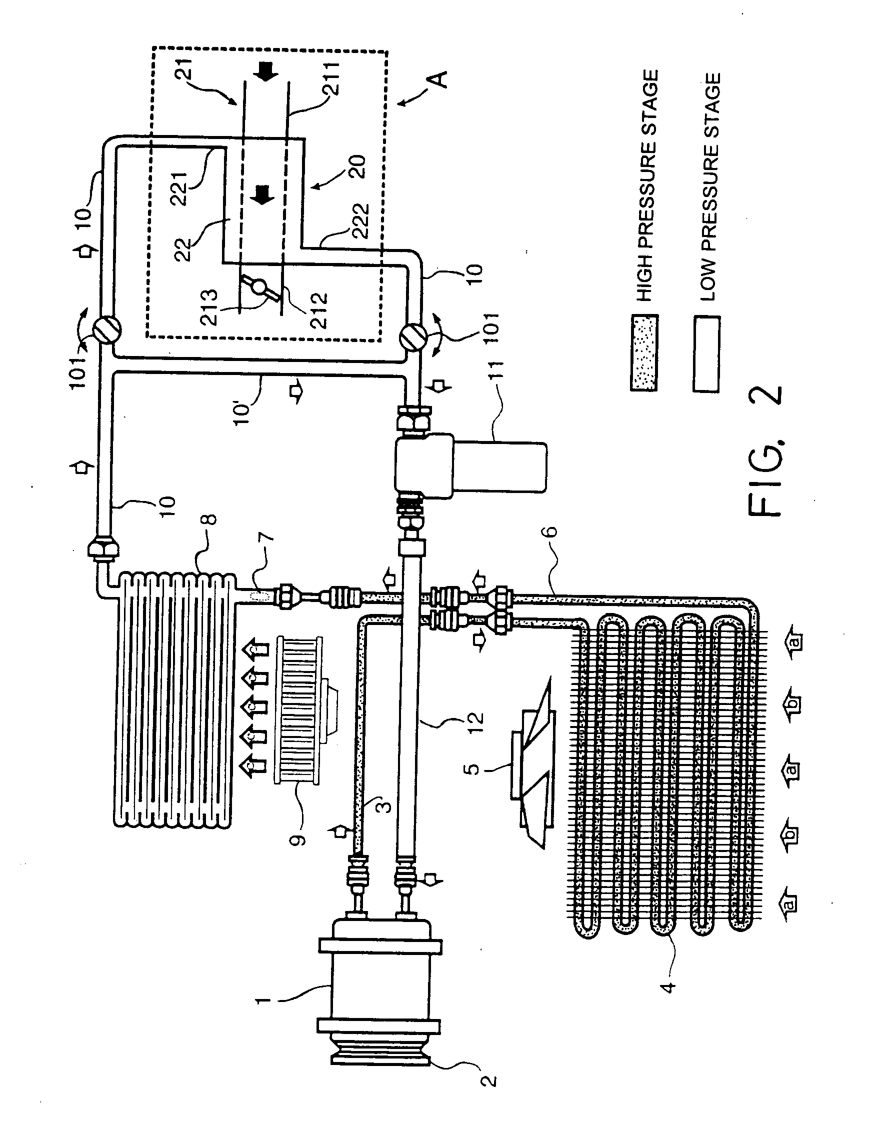
[0015] Referring to FIG. 1, a cooling system with refrigerant according to the present invention includes a compressor 1, a pulley 2, a condenser 4, a connecting pipe 3, which is disposed between the compressor 1 and the condenser 4, a fan 5 for the condenser 4, an expansion valve 7, an evaporator 8, a connecting pipe 6, which is disposed between the condenser and the evaporator 8, a cold air fan 9, a dehumidifying water collector 11, a connecting pipe 10, which is disposed between the evaporator and the dehumidifying water collector and a connecting pipe 12, which is disposed between the dehumidifying water collector and the compressor. The preceding components are basic elements required for constituting a car room of an air conditioning system. The route from the compressor 1 and the connecting pipe 3 to the expansion valve 7 via the condenser 4 is a high pressure stage and the route after the expansion valve 7 to the connecting pipe 12 via the evaporator 8 is a low pressure stag...


PUM


Abstract

A cooling system with refrigerant for air conditioning and engine parts, comprising: a compressor, a high pressure circuit filled with the refrigerant; and a low pressure circuit filled with the refrigerant too. The high pressure circuit further comprises a condenser, the low pressure circuit further comprises an evaporator and a heat exchanger, the heat exchanger at an interior thereof is provided with a refrigerant passage and a fluid passage, which enters the engine, with the two passages next to each other and contacting with each other and at an exterior thereof includes a refrigerant inlet, a refrigerant outlet, a fluid entrance to the engine and a fluid exit from the engine. Once the compressor is in a state of running, the refrigerant in the low pressure circuit passes through the evaporator and enters the refrigerant passage in the engine via a connecting pipe in the low pressure circuit and the refrigerant inlet and then flows out from the heat exchanger via the refrigerant outlet; a fluid for being cooled flows into the fluid passage via the fluid entrance and flows out from the fluid exit before reaching an engine body; and temperature of the fluid during entering fluid passage is higher than the refrigerant in the refrigerant passage and heat in the fluid transmits the refrigerant between a wall of the fluid passage and a wall of the refrigerant passage.

Description

BACKGROUND OF THE INVENTION [0001] 1. Field of the Invention [0002] The present invention relates to a cooling system for a car engine system / device, and particularly to a cooling system / device, in which an ordinary car room air conditioning system with refrigerant, a compressor, heat dissipating fins and pipeline for circulating the refrigerant is utilized and expanded to provide a function of engine system cooling in addition to the car room air conditioning. [0003] 2. Description of Related Art [0004] The conventional car room air conditioning system, which includes refrigerant, a compressor, heat dissipating fins and pipeline for circulating the refrigerant, usually only provides a function of cooling car room space and not for cooling the engine system. On the other hand, the engine system generally is cooled by way of water circulation of the water box system passing through the engine body (water cooling type) or part of outside air being guided to the engine blowing the diss...

Claims


Application Information

Patent Timeline
IPC IPC(8): B60H1/32F01P9/06F02B29/04F02M31/20F25B5/04F25B27/00F25B40/06
CPCB60H2001/3289Y02T10/126F01P2060/02F01P2060/04F02B29/0443F02B29/0462F02M31/20F25B5/04F25B27/00F25B40/06F25B2327/001F25B2400/0409F28D2021/0082F28D2021/0089Y02T10/146F01P9/06Y02T10/12
Inventor LIN, TZU-TANG
Owner LIN TZU TANG
Why Eureka
Try Eureka