Automatic transmission, dynamo-electric machine, and car

a technology of automatic transmission and dynamoelectric machine, which is applied in the direction of engine starters, vehicle sub-unit features, and gearing, etc., can solve the problems of inability to principally perform torque transfer, inability to control stably, and inability to inevitably shorten the life of the engine, so as to achieve continuous torque adjustment, save fuel, and the effect of constant torque adjustmen

Inactive Publication Date: 2005-04-07
HITACHI LTD
View PDF14 Cites 25 Cited by
  • Summary
  • Abstract
  • Description
  • Claims
  • Application Information

AI Technical Summary

Benefits of technology

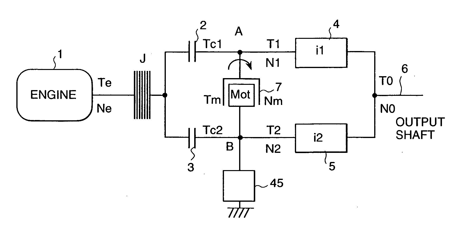
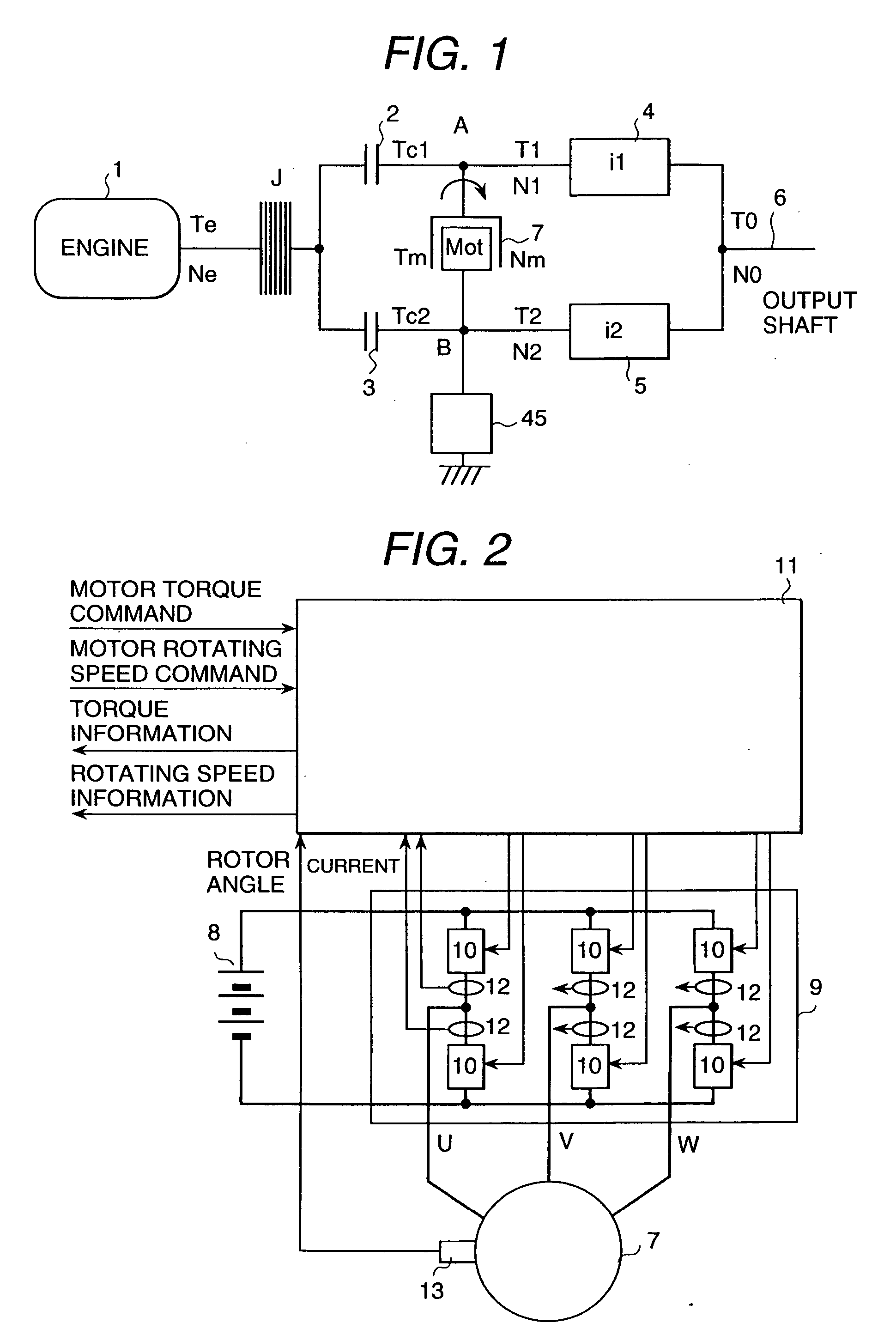
A second object of the present invention is to reduce relatively the cost for the overall functions by enabling the creep control and the pull-out control with an identical means as well as the transmission control.
In addition, by making the best use of potential for controlling the torque of the traction shaft with the toque generated by the electric motor, the control for a extremely low-speed running, that is, a creep running without engine operation, saving the fuel by shutting off the engine while the automobile stops and then restarting the engine while the automobile runs again is realized, and the control for adjusting the torque continuously and smoothly when altering the forward movement and the backward movement is realized.

Problems solved by technology

In case of shifting down gears, even if the transmitting torque of the next-stage clutch is made decrease, it is not principally possible to perform the torque transfer from the high gear position with a lower energy potential to the lower gear position with a high energy potential.
However, in this method, there is such a disadvantageous aspect that the clutch plate is damaged due to its friction and thus its life time becomes inevitably short.
In addition, according to this method, as the torque transmitting power is controlled by adjusting the friction force and the friction force has a negative resistance characteristics with respect to the relative speed, it is extremely difficult to control stably the torque transmitting power in a designated value, which leads to shift shock due to the generation of judder and even in the worst case, the clutch plate may be worn away with a rippled surface.
For this reason, the response from pressing the accelerator to reaching a designated torque is so slow that the drivability is not good.

Method used


Image

  • Automatic transmission, dynamo-electric machine, and car
  • Automatic transmission, dynamo-electric machine, and car
  • Automatic transmission, dynamo-electric machine, and car

Examples


second embodiment

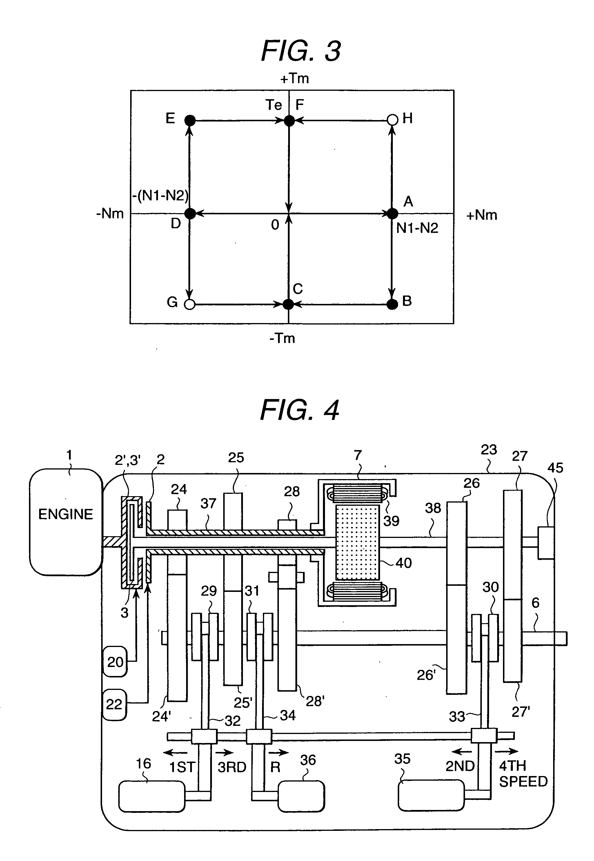
The engine load control by the motor torque after engine starting-up and the clutch synchronizing control with reference to the motor speed are equivalent to the operations for shifting up gears as described in the second embodiment, which corresponds to the torque phase and the inertia phase, respectively, considered as the 0-to-1 gear shift operation. Therefore, as this process is related to the potential energy moving from high level to low level, the engine output during this process is used for charging the battery and gradually transfer the energy to the output shaft. There is such as effect that this control can be performed even if the battery remaining is small, and that the reliability can be increased.

By means that the battery remaining information is supplied into the automobile starting control part 46 in the block diagram of FIG. 10, if the battery remaining is larger, the automobile starting control is performed in the method of the forth embodiment in order to incre...

ninth embodiment

the present invention reduce the emission of the injurious ingredient in the exhaust gas immediately after starting the engine, and its control procedure is shown in FIG. 20. The structure of the transmission used in this embodiment is identical to that shown in FIG. 10. The control method of the structure element is identical to the method in the first embodiment. By referring to FIG. 10 and FIG. 20, the control scheme of the exhaust gas reduction control is described.

If the key switch is turned into the starting position while the select lever is staying at P-range, the engine temperature is judged in Step 1, and if the temperature is below the preset value, the reverse gear is engaged in Step 2 and the first clutch is engaged in Step 3. When the motor torque instruction part 14 generates the automobile starting torque instruction in Step 4, as the stator 39 of the electric motor 7 rotates the output shaft 37 of the first clutch, it rotates the engine through the first clutch 2. ...

tenth embodiment

FIG. 21 is a flow chart of R-to-D or D-to-R selection control of the present invention, and FIG. 22 shows a time chart of its individual waveform data. The transmission to be used is assumed to be as shown in FIG. 17. For example, suppose that R-to-D selection is performed while the automobile moves backward and then it continues to run in the forward direction. This way of running the automobile is such a familiar driving pattern that the automobile moves backward outside the garage and turns its direction, and that is called switch turn.

The process from the engine starting to the automobile starting while moving backward are described with the steps up to Step 11 of FIG. 18 in the embodiment 6. Assuming that the select lever is changed to D-range during the reverse running and with the acceleration pedal being pressed, the engine torque and the engine speed are supposed to be kept constant. The range is judged in Step 1 of FIG. 21, and if the range is D-range, the motor speed is ...


PUM


Abstract

A transmission, by means of inserting an electric motor between a couple of clutch shafts of twin-clutch type automatic transmission and controlling the torque and speed of the electric motor, establishing a smooth and efficient gear shifting control as well as enable to realize a creep control, idling stop starting control, R-to-D, D-to-R selecting control. The pre-stage gear is released after the torque transfer is completed with the electric motor, and the clutch is exchanged after synchronizing the motor speed with the electric motor. As the friction control of the clutch is not performed, smooth gear shift work can be realized, and the same control scheme extends to creep control, idling stop starting control, R-to-D, D-to-R selecting control to be enabled, which leads to such an effect that the life is extended without the clutch being worn away, as well as the drivability can be increased remarkably. As a single transmission can realize multiple functions, there is such an effect that the overall cost can be reduced relatively.

Description

TECHNICAL FIELD The present invention relates to a automatic transmission for the automobile enabling the electric motor control and the regenerative braking, and its control method and an automobile using this transmission. BACKGROUND ART In general, automatic transmissions using a planetary gear or a transmission mechanism with parallel counter shaft are used in the conventional automatic transmissions, in which the clutches installed at the individual gear trains having their own different gear ratio are selectively engaged in order to shift gears. This prior art is disclosed, for example, in Japanese Patent Laid-Open Number 10-89456 (1998). The result of analyzing the above prior art is described below. The analyzing result shown below is not a straight forward description of the prior art but shown as the analyzing result. In case of shifting up gears, as the next-stage clutch is started to be engaged and the torque transmitting power is gradually made increase in a partial...

Claims


Application Information

Patent Timeline
Patent Type & Authority Applications(United States)
IPC IPC(8): B60K6/20B60K6/48B60K6/547B60L50/16B60W10/00B60W10/02B60W10/04B60W10/06B60W10/08B60W10/10B60W10/11B60W10/113B60W10/12B60W10/18B60W10/184B60W20/00F02D29/02F02N11/00F02N11/04F16D48/02F16H3/12F16H59/08F16H59/74F16H61/02F16H61/04F16H61/20F16H61/688F16H63/40
CPCB60K6/48Y10T477/26B60K2006/262B60L2240/421B60L2240/423B60L2240/486B60W10/02B60W10/08B60W10/113B60W30/18127B60W2510/081B60W2510/1005B60W2510/104B60W2540/10B60W2540/12B60W2710/081B60W2710/083B60Y2400/428B60Y2400/608F16H3/006F16H3/126F16H61/0246F16H61/0403F16H61/20F16H61/688F16H2059/088F16H2061/0411F16H2061/0422F16H2061/0433F16H2200/0043F16H2306/44F16H2306/48F16H2306/52F16H2306/54F16H2312/00F16H2312/06F16H2312/14Y02T10/6221Y02T10/642B60K6/383B60K2006/381Y10S903/93Y10T74/19288Y10T477/27Y10T477/33Y10T74/19251Y10T74/19284Y10T477/24B60K6/547Y02T10/62Y02T10/64B60W30/18063
Inventor IBAMOTO, MASAHIKOKUROIWA, HIROSHI
Owner HITACHI LTD
Why Eureka
Try Eureka