
Solar cell device

Inactive Publication Date: 2005-04-07
3GSOLAR PHOTOVOLTAICS
View PDF27 Cites 185 Cited by
  • Summary
  • Abstract
  • Description
  • Claims
  • Application Information

AI Technical Summary

Benefits of technology

[0045] According to still further features in the described preferred embodiments, the at least partially transparent conductive coating includes tin oxide, and the electrical resistance of the coating exceeds 30 ohms per square. Preferably, a low-cost, low-grade tin oxide coating can be used, having an electrical resistance exceeding 50 ohms per square, and even exceeding 50 ohms per square.

Problems solved by technology

It is further argued that there might be significant cost savings over classical single crystal or polycrystalline silicon cells and even more recent thin-film photovoltaic cells, since these are all high cost and rely on expensive and often environmentally problematic raw materials, together with complex, costly, semiconductor industry processing equipment and production techniques.
These drawbacks include the use of vacuum deposition and laser methods, clean-room protocols, use of toxic hydrides such as silane, phosphine etc., as raw materials, and the use of toxic active-layer materials containing cadmium, selenium or tellurium.
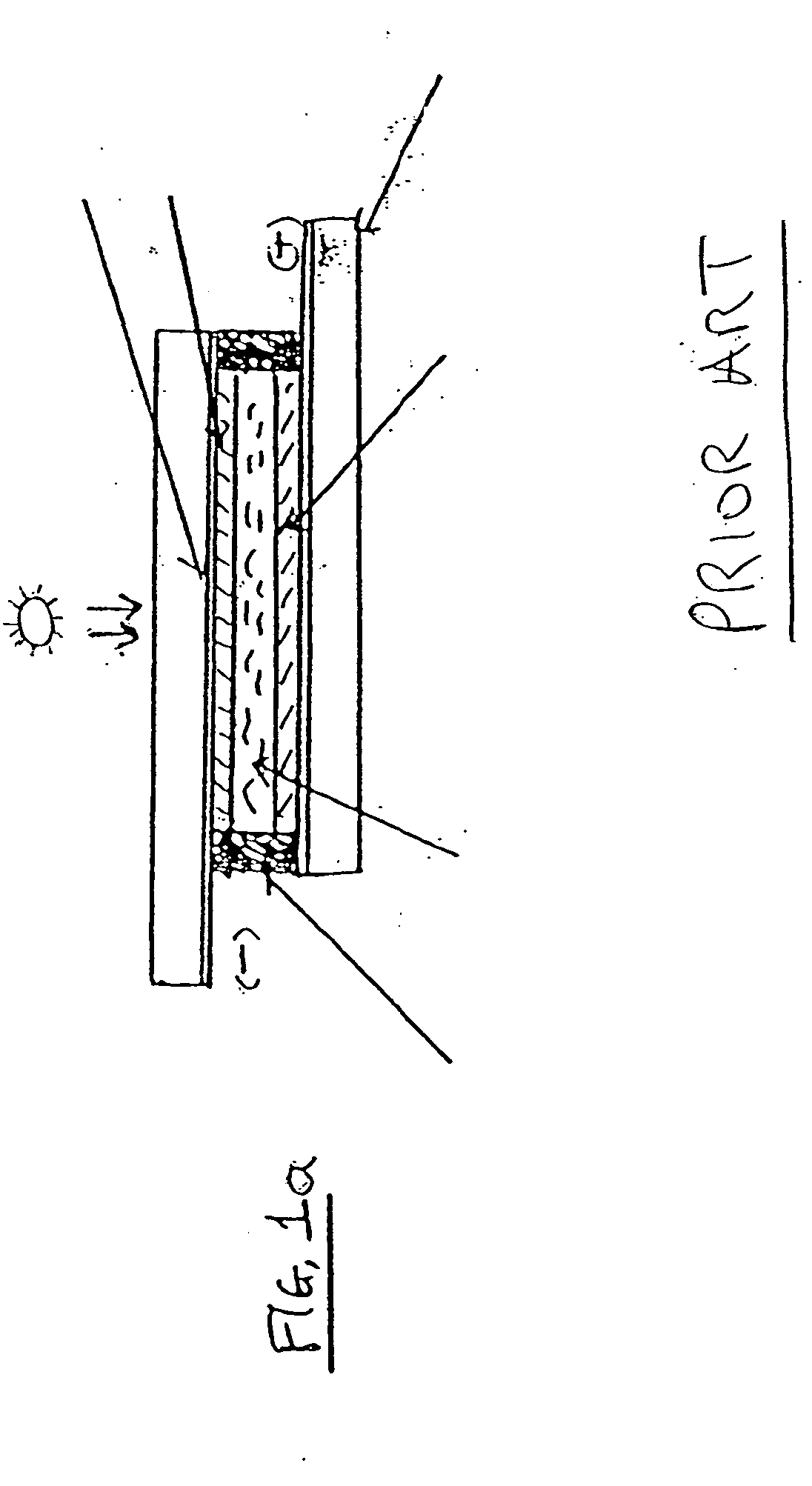
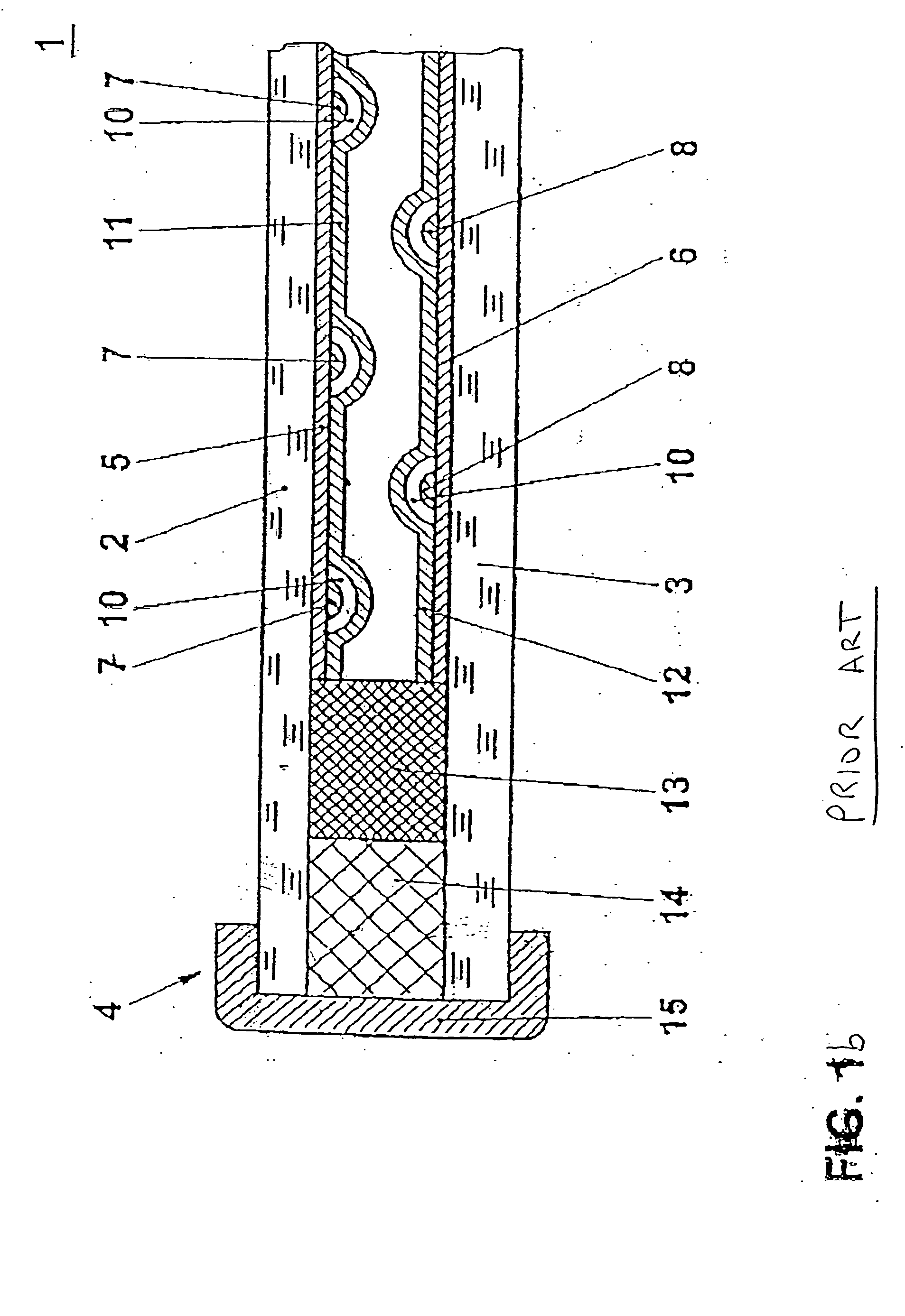
The ohmic loss via the conductive glass coated with tin oxide is a major problem of such cells.
The tin oxide coating is extremely thin, being limited in thickness usually to below one micron due to the need to maintain a high light transmittance through to the dye / titania layer of the photoanode.
Moreover, tin oxide is only semi-conductive and is mechanically weak, such that the current takeoff is significantly limited by such a cell design.
Furthermore, the emphasis is on single cell construction with no advantage offered for construction of a multi-cell module.
Most significantly, the periphery (i.e., the sides) of the cells is devoid of any current takeoff means, any current takeoff being made on the active sun-facing surface of the cell, resulting in a waste of available area.
Consequently, the improvement in the cell performance is far from sufficient.
However, no means for protecting the conductors from corrosion are taught.
More importantly, there is no specific means described for achieving the requisite current takeoff without wasting available area.
To date, there has been no real commercialization of photovoltaic dye cells, despite the great techno-economic potential thereof.
The principal problems remaining include scale-up of cells to widths much above one centimeter—and areas much above 50 sq. cm—due to excessive ohmic losses from the poorly conducting tin oxide layers on the glass or plastic, long term stability of the dye, and difficulties of sealing the cells against long-tenm dryout and performance degradation.
A further problem in prior art cells and modules has been excessive surface area wasted in seals and conducting paths on the sun-facing side of the cell or module.
The active current-producing area in such cases is often less than 70% of the geometric area (footprint) of the cell or module, providing a poor effective efficiency from the available area.

Method used


Image

  • Solar cell device
  • Solar cell device
  • Solar cell device

Examples


Embodiment Construction

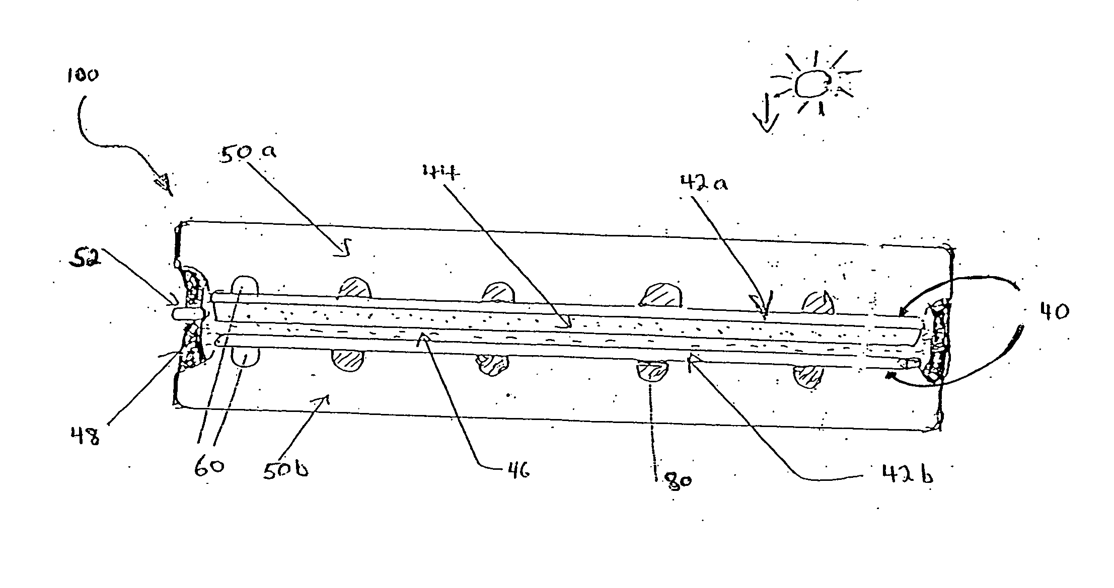
[0074] The principles and operation of the photovoltaic cells according to the present invention may be better understood with reference to the drawings and the accompanying description.

[0075] Before explaining at least one embodiment of the invention in detail, it is to be understood that the invention is not limited in its application to the details of construction and the arrangement of the components set forth in the following description or illustrated in the drawings. The invention is capable of other embodiments or of being practiced or carried out in various ways. Also, it is to be understood that the phraseology and terminology employed herein is for the purpose of description and should not be regarded as limiting.

[0076] The present invention overcomes these and other problems and paves the way to the manufacture of an efficient, commercially viable device. Various aspects and embodiments of the present invention are described hereinbelow:

[0077] One aspect of the presen...


PUM


Abstract

A photovoltaic cell for converting a light source into electricity, including: (a) a housing for the photovoltaic cell, including: (i) an at least partially transparent cell wall; (b) at least one electrically-conductive element, disposed at least partially within the photovoltaic cell, for boosting collection of a current generated by the cell; (c) a conductive coating, electrically associated with the electrically-conductive element, and disposed on a surface within the photovoltaic cell; (d) an electrolyte, disposed within the cell wall, the electrolyte containing a redox species, and (e) a current collection element, disposed on a side of the cell wall, wherein the current collection element is electrically connected to the electrically-conductive element, so as to remove the current produced by the cell.

Description

[0001] This application draws priority from Israel Patent Application Serial No. 153,895, filed Jan. 12, 2003. FIELD AND BACKGROUND OF THE INVENTION [0002] The present invention relates to photovoltaic cells (also known as solar cells) for producing electricity from sunlight, and for improved systems and methods therefor. [0003] The invention has particular relevance for solar cells of the dye sensitized type, and is applicable to other types of solar cells, and devices such as screen displays and electronic or defrostable windows where a high current density of operation at minimal ohmic loss is advantageous. A further application is in solar thermal systems (e.g., solar water heaters) where heat and power may be provided from the same collector area / structure. [0004] Dye-sensitized photovoltaic cells for producing electricity from sunlight have been disclosed by U.S. Pat. No. 5,350,644 to Graetzel, et al. U.S. Pat. No. 5,350,644 teaches a photovoltaic cell having a light-transmitt...

Claims


Application Information

Patent Timeline
IPC IPC(8): F24JH01L25/00
CPCH01G9/2031Y02E10/542H01G9/2068Y02B10/10H01G9/2018H01G9/2077
Inventor GOLDSTEIN, JONATHAN R.
Owner 3GSOLAR PHOTOVOLTAICS
Learn More