Film stretching apparatus and solution film-forming method

a film-forming method and film-strength technology, applied in dough shaping, manufacturing tools, food shaping, etc., can solve the problems of high volatility, inability to hold lateral edge portions properly, and inability to provide polymer films to satisfy such requirements

Inactive Publication Date: 2005-04-07
FUJIFILM CORP +1
View PDF4 Cites 16 Cited by
  • Summary
  • Abstract
  • Description
  • Claims
  • Application Information

AI Technical Summary

Benefits of technology

[0021] According to the present invention, since the first holder holds the lateral edge portion of the polymer film and a second holder the lateral portion of the polymer film that is inside of the lateral edge portion, it is possible to ensure to hold the film without causing failure in holding or breakage in film edge, even if the lateral edge portions are curled. Moreover, since the first holder holds the lateral edge portion of the polymer film before the second holder holds the lateral portion of the polymer film, it is possible to feed the soft polymer film before drying process without causing the breakage in the polymer film. Furthermore, the first biasing member to press the flapper toward the second hold position makes it possible to set the flapper at the second hold position securely and quickly.

Problems solved by technology

The solution film-forming method using the above conventional tenter apparatus can not provide polymer films to satisfy such requirements.
For instance, since thin and wide polymer film tends to be curly in the widthwise direction, the clip would not be able to hold properly the lateral edge portions of the polymer film, and thereby, the lateral edge portion of the polymer film may be folded by the clips.
Moreover, increasing the film-forming speed causes higher volatility of the solvent of the polymer solution at the time when the clips start to hold the polymer film, and thus the clips cannot hold the polymer film properly.
Especially, since the polymer film before the drying step becomes softer due to high film-forming speed, the clips may break the lateral edge portion of the polymer film.
This method, however, needs to provide both the pins and the clips so that the tenter apparatus will be more complicated.
Moreover, even the pins may not be able to hold the polymer film properly if the lateral edge portions of the polymer films are largely curled.

Method used


Image

  • Film stretching apparatus and solution film-forming method
  • Film stretching apparatus and solution film-forming method
  • Film stretching apparatus and solution film-forming method

Examples


embodiment 1

[0090] Embodiment 1

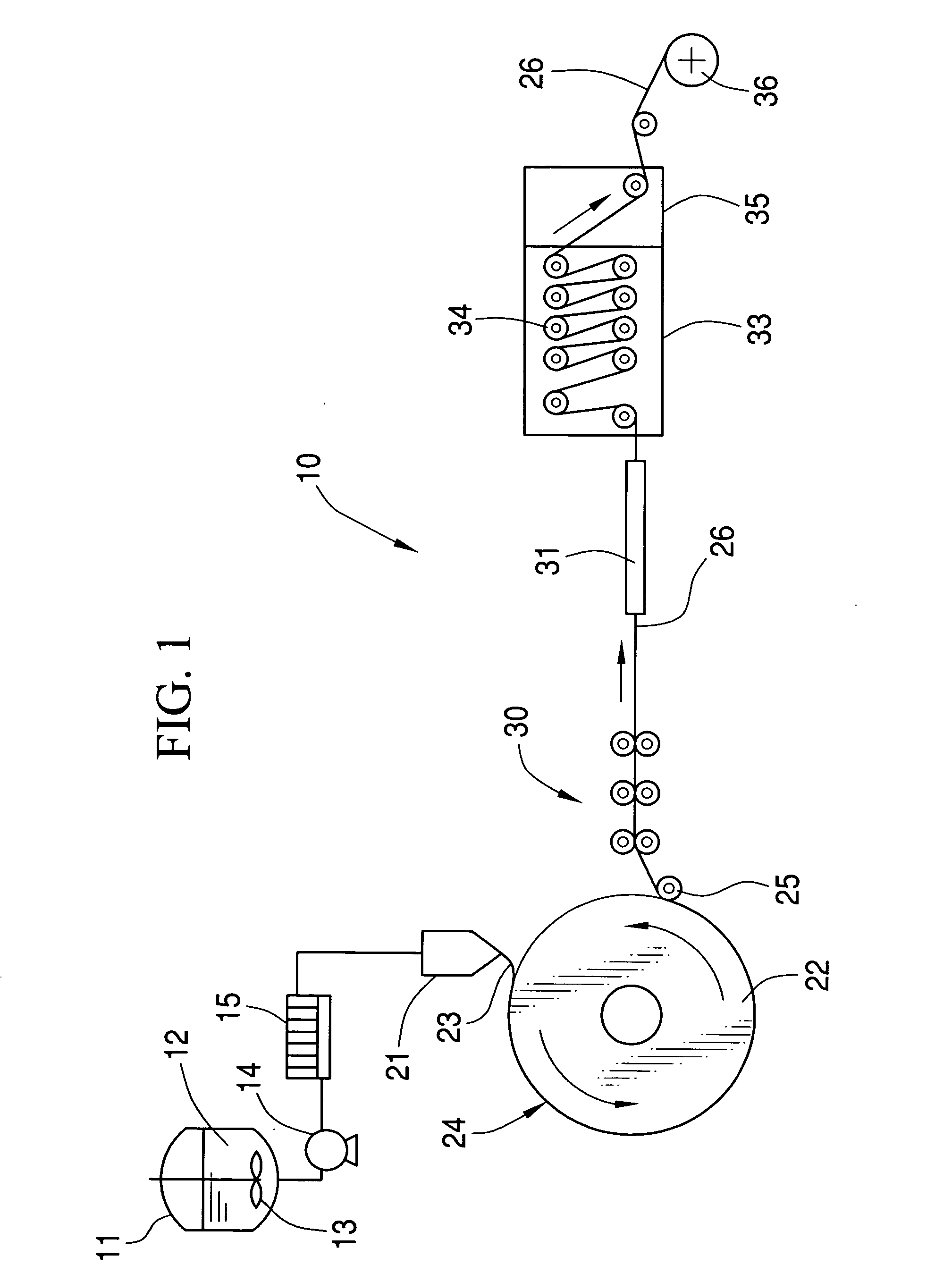
[0091] In the solution film-forming facility 10 shown in FIG. 1, cellulose triacetate film is formed by use of the tenter apparatus 111 having the clips 115 shown in FIGS. 13-19. In producing the cellulose triacetate film, the co-casting die in FIG. 10 is used to cast the dope. The combinations of the materials for the dopes (A-type and B-type) are listed in Table 1. The A-type dope is used for the core layer of the cellulose triacetate film, and the B-type dope is used for the front and rear surface layers to sandwich the core layer. The dope casting speed is controlled such that the thickness of the film product (cellulose triacetate film) is 40 μm after stretching by the tenter apparatus 111. The film forming speed is 70 m / min, and the film peeling speed (film speed by the rotary drum 22) is 58 m / min. In the tenter apparatus 111, the film 26 is stretched by 1.2 times in the film feeding direction, and 1.5 times in the widthwise direction that is perpendicular t...

embodiment 2

[0105] Embodiment 2

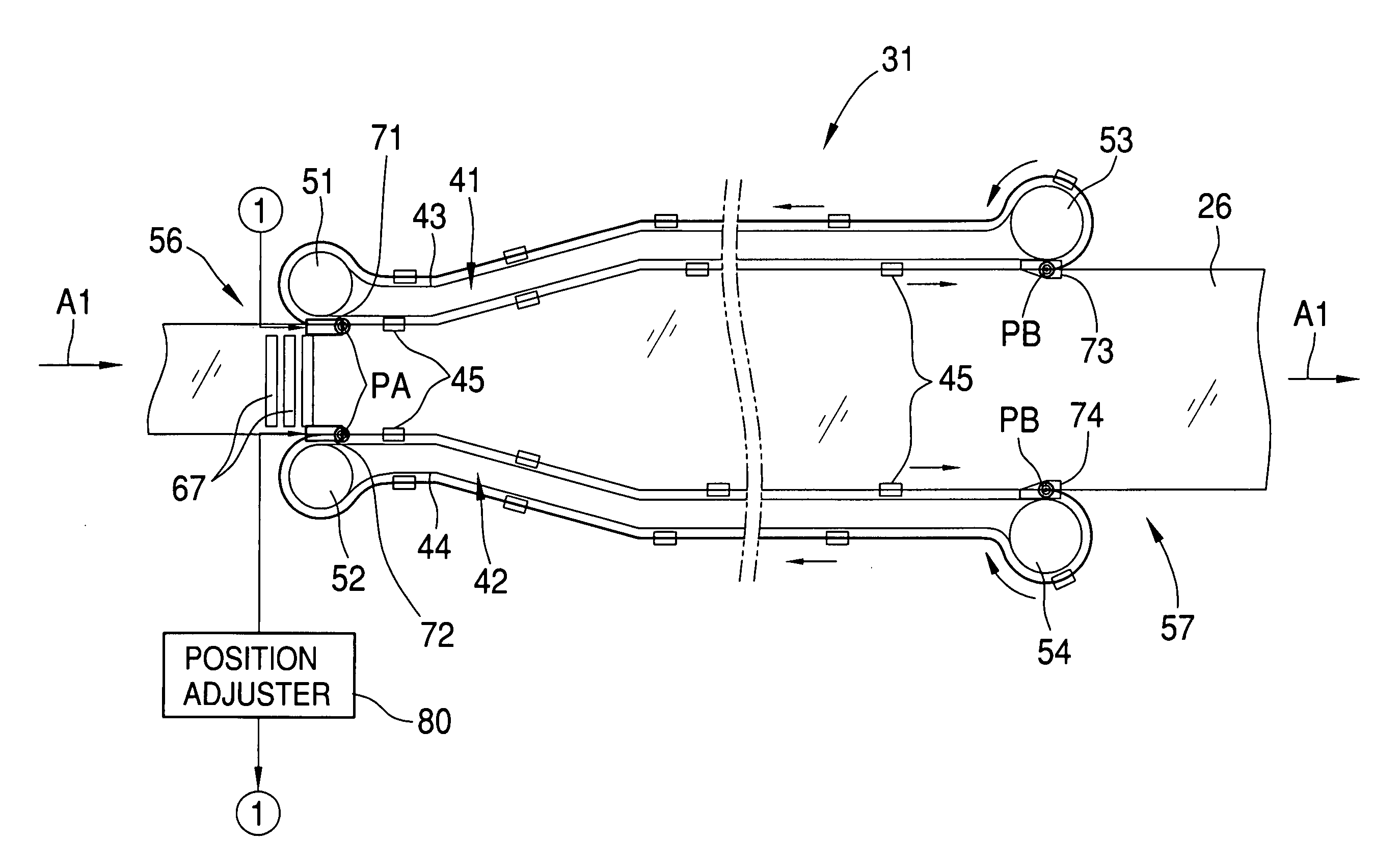
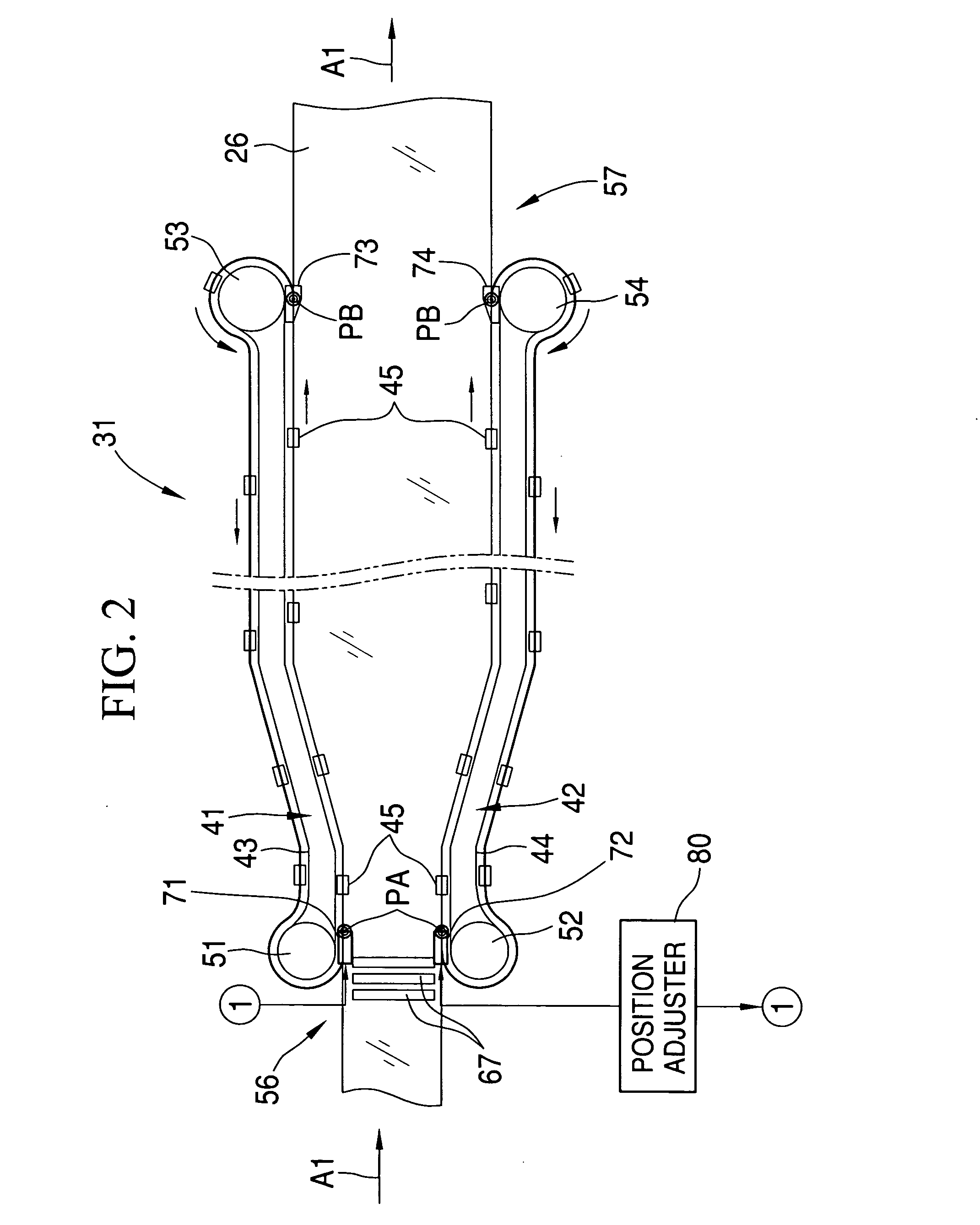
[0106] In the solution film-forming facility 10 shown in FIG. 1, cellulose triacetate film is formed by use of the tenter apparatus 31 having the clips 45 shown in FIGS. 2-9. Other film-forming conditions are the same as Embodiment 1. The results of the film inspection are the same as Embodiment 1.


PUM

PropertyMeasurementUnit
widthaaaaaaaaaa
temperatureaaaaaaaaaa

Abstract

A clip to hold the film has a clip body, a flapper, a press slider and a rail mount. A pair of the press sliders is located in both sides of the flapper. A coil spring presses the press slider upward. A pair of entrance side film release members, provided in the tenter entrance, presses the press slider downward to press the lateral edge portions of the film by the press sliders. At the film hold position, the flapper rotates from a release position to a hold position to hold the film, and the flapper is kept at the hold position by a torsion spring. The flapper holds the film 26 after the press slider holds the lateral edge portions of the film, so the flapper can hold the film even when the lateral edge portions of the film are curled.

Description

BACKGROUND OF THE INVENTION [0001] 1. Field of the Invention [0002] The present invention relates to a film stretching apparatus and a solution film-forming method that is preferably used for manufacturing polymer films for optical purposes such as liquid crystal devices, organic electro luminescence and polarizing plates. [0003] 2. Description of the Related Art [0004] Polymer films for use in optical purposes are generally manufactured by a solution film-forming method including the steps of casting a polymer liquid (dope) on a support from a casting die, peeling the solidified dope (polymer film) from the support, drying the film and winding the solidified film. [0005] In order to improve the flatness, mechanical strength and optical properties of the polymer film, Japanese Patent Laid-Open No. 62-115035 describes a tenter apparatus to stretch the polymer film and regulate the width of the polymer film. Such tenter apparatus is provided in the drying step, so the polymer film is ...

Claims


Application Information

Patent Timeline
Patent Type & Authority Applications(United States)
IPC IPC(8): B29C55/02B29C55/08B29C55/06B29C55/16B29C55/20B29D7/01
CPCB29C55/023B29C55/06B29K2001/00B29C55/20B29D7/01B29C55/165B29C55/02
Inventor YAMAZAKI, HIDEKAZUFUJIMOTO, SADANOBUARAI, TOSHINAO
Owner FUJIFILM CORP
Why Eureka
Try Eureka