Imaging system for robotically inspecting gas turbine combustion components

a gas turbine and combustion component technology, applied in the direction of instruments, machines/engines, fluorescence/phosphorescence, etc., can solve the problems of reducing the efficiency or damage of the turbine, the maximum temperature of the exhaust gas is normally limited, and the cost of repair is high

Inactive Publication Date: 2005-04-07
GENERAL ELECTRIC CO
View PDF15 Cites 63 Cited by
  • Summary
  • Abstract
  • Description
  • Claims
  • Application Information

AI Technical Summary

Problems solved by technology

However, the maximum temperature of the exhaust gases is normally limited by the materials used to fabricate the hot section components of the turbine.
Defects in the TBC consist primarily of cracks, spalls, and erosion.
These defects can be caused by various operational conditions such as thermal and mechanical fatigue, and by contamination from foreign debris in the gas stream.
Defects left uncorrected can cause reductions in turbine efficiency or component damage resulting in expensive repairs.
If not rectified, these conditions could lead to reduced machine efficiency and damage to the turbine that may result in unplanned outages and significant repair costs.
Removal and installation of transition pieces is the most time-intensive operation of the combustion inspection.
This operation contributes most significantly to the combustion inspection outage duration and corresponds directly to time lost producing power.
Such prior inspection practices have many disadvantages, including the time required for disassembly and installation, the lack of direct retrievable defect data for engineering evaluation and historical comparison and complete reliance on human factors.

Method used


Image

  • Imaging system for robotically inspecting gas turbine combustion components
  • Imaging system for robotically inspecting gas turbine combustion components
  • Imaging system for robotically inspecting gas turbine combustion components

Examples


Embodiment Construction

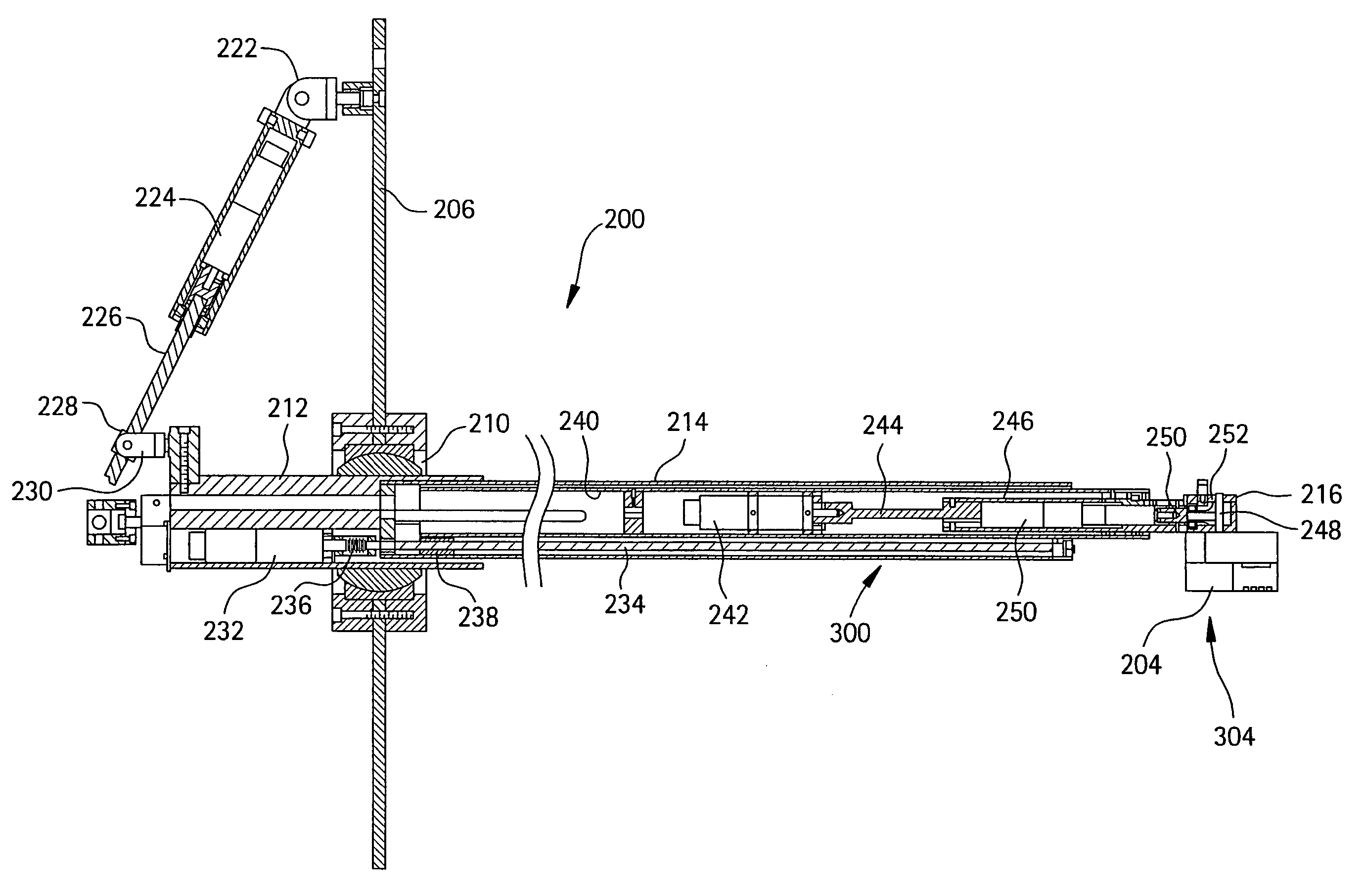
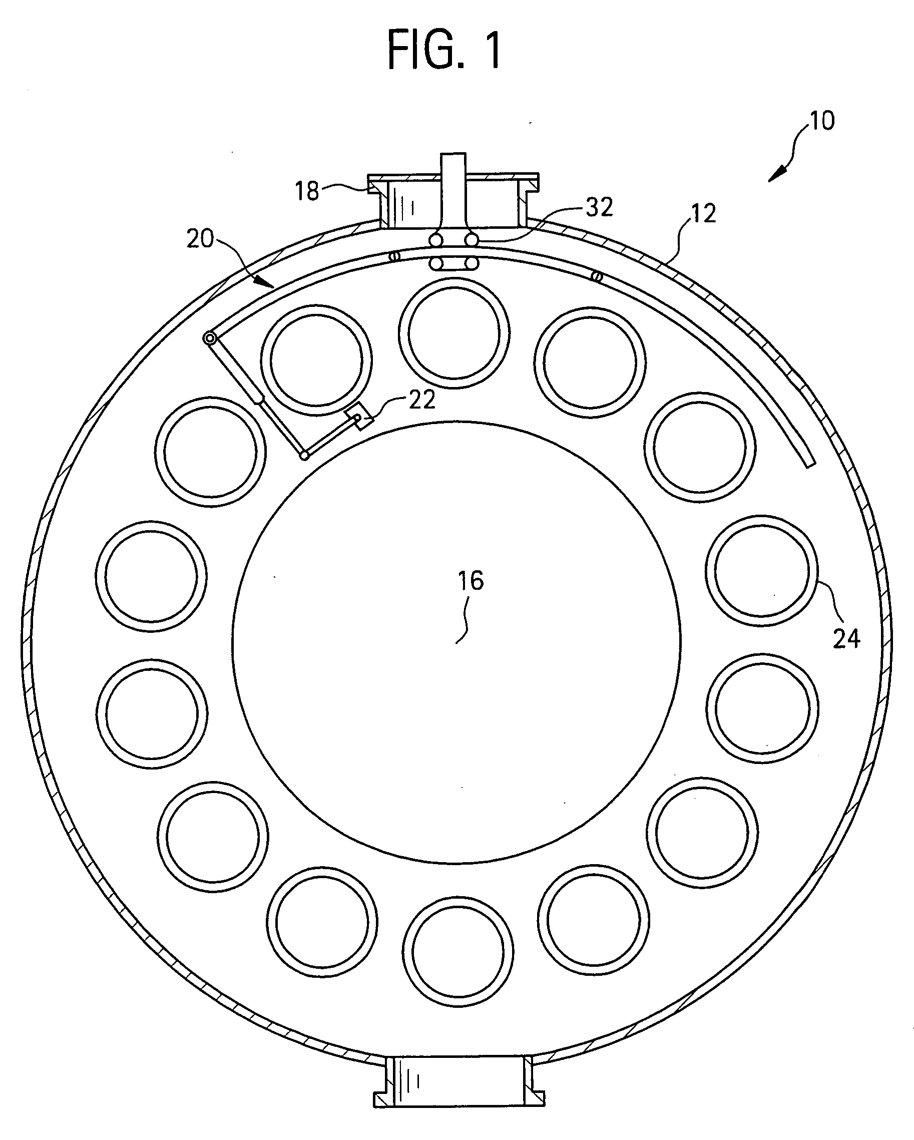
[0019] Referring now to the drawings, particularly to FIG. 1, there is schematically illustrated an axial view of a gas turbine, generally designated 10, having an outer casing 12 and an annular array of combustors including combustion flow sleeves 14 within the casing 12. The rotational axis of the gas turbine rotor, not shown, is indicated at 16. Also illustrated in FIG. 1 is an access opening or manhole 18 through which an external manipulator, generally designated 20, is inserted for inspecting the external surface of each of the impingement sleeves of the transition pieces. By manipulating the external manipulator 20, an inspection head 22 may be displaced axially the full length of the impingement sleeve as well as positioned at any location about the entire external peripheral surface of the impingement sleeve.

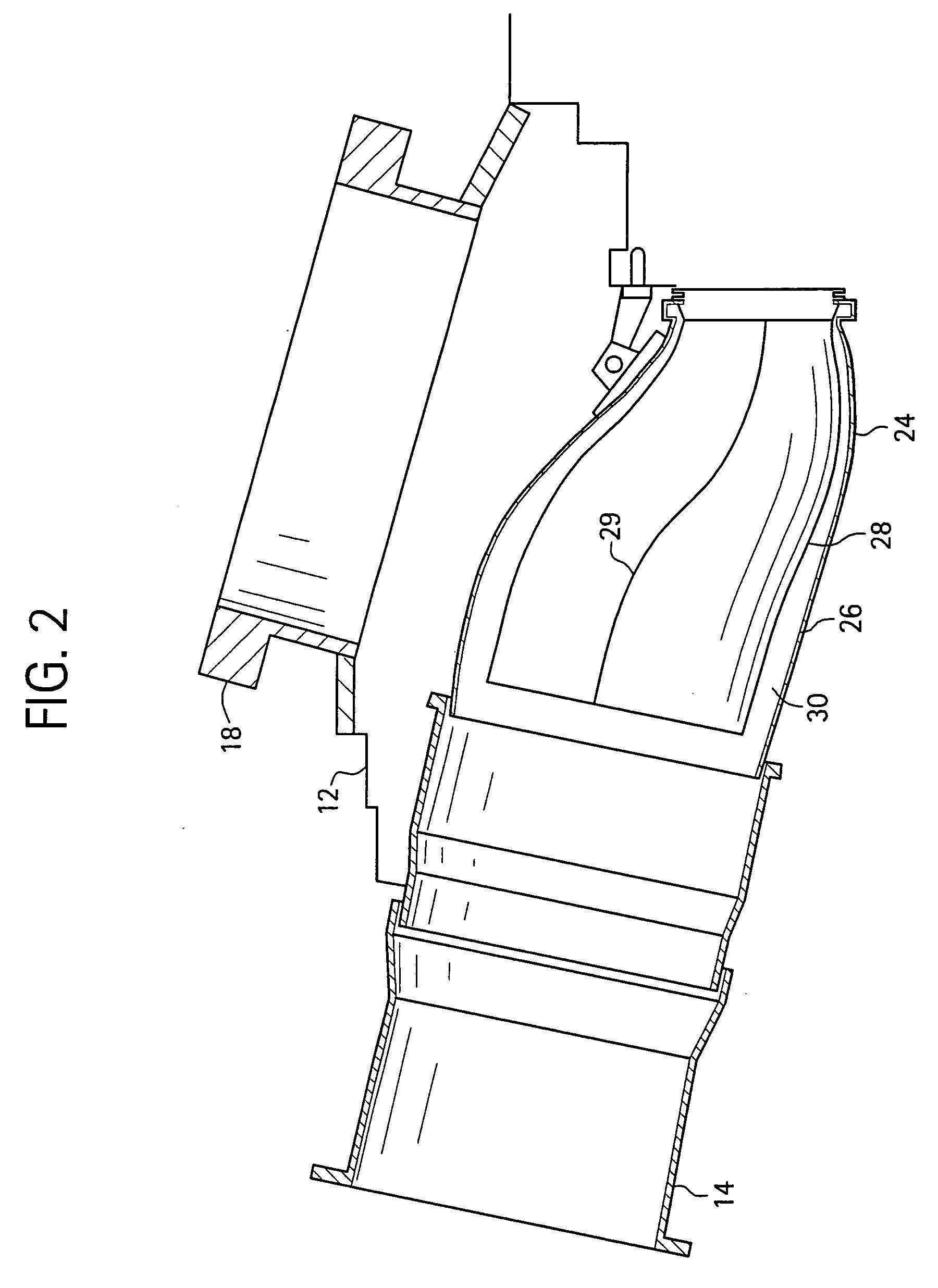
[0020] Referring now to FIG. 2, there is illustrated a flow sleeve 14 and a transition piece 24, the transition piece including an impingement, i.e., perforated sleeve...


PUM

PropertyMeasurementUnit
wavelengthaaaaaaaaaa
angleaaaaaaaaaa

Abstract

A system for in situ inspection of a surface of a hot gas component of a turbine includes a robot having an elongated inspection arm extending toward the surface of the hot gas component; and an inspection head carried adjacent an end of the inspection arm remote from controls for the robot. The inspection head is manipulated by the inspection arm to locate the inspection head adjacent interior wall portions defining the hot gas component including by displacing the inspection head in a generally axial direction and generally radially toward a wall portion of the hot gas component being inspected. The inspection head is configured with a UV system to excite and detect fluorescence from a taggant material disposed in a coating on the hot gas component.

Description

BACKGROUND OF THE INVENTION [0001] The present invention relates to a robotic inspection system for in situ inspection of gas turbine annular combustion components for the purpose of evaluating the condition of the components. [0002] In gas turbine engines, for example, power turbines, air is drawn into the front of the engine, compressed by a shaft-mounted rotary compressor, and mixed with fuel. The mixture is burned, and the hot exhaust gases are passed through a turbine mounted on a shaft. The flow of gas turns the turbine, which turns the shaft and drives the compressor. The hot exhaust gases flow from the back of the engine, turning a secondary turbine which in turn drives a generator. [0003] During operation of gas turbine engines, the temperatures of combustion gases may exceed 3,000° F., considerably higher than the melting temperatures of the metal parts of the engine, which are exposed to these gases. The metal parts that are particularly subject to high temperatures, and ...

Claims


Application Information

Patent Timeline
Patent Type & Authority Applications(United States)
IPC IPC(8): F01D21/00G01N3/06G01N3/56G01N21/64G01N21/88G01N21/954
CPCF01D21/003G01N3/567G01N21/6447G01N21/8803F05D2260/80G01N2203/0647Y02T50/67Y02T50/671G01N21/954Y02T50/60
Inventor DEVITT, JOHN WILLIAMFERREIRA, CUSTODIO J.S.
Owner GENERAL ELECTRIC CO
Why Eureka
Try Eureka