
Wavelength selective switching device and method for selectively transmitting optical signals based on wavelength

a wavelength selective switching and optical signal technology, applied in the field of optical devices, can solve the problem that the wavelength selective switching device cannot be used in a conventional reflective configuration, and achieve the effect of reducing the size of the devi

Inactive Publication Date: 2005-04-07
AVAGO TECH WIRELESS IP SINGAPORE PTE
View PDF10 Cites 6 Cited by
  • Summary
  • Abstract
  • Description
  • Claims
  • Application Information

AI Technical Summary

Benefits of technology

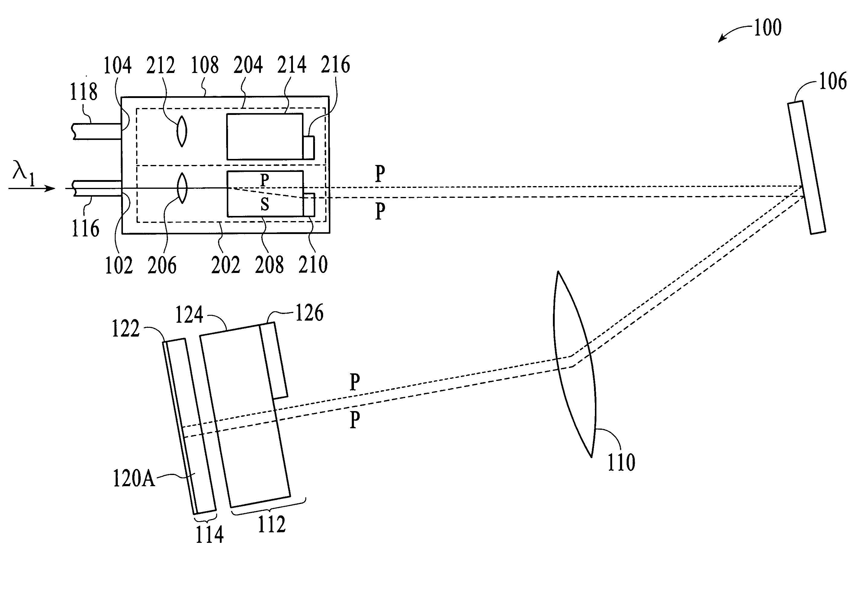
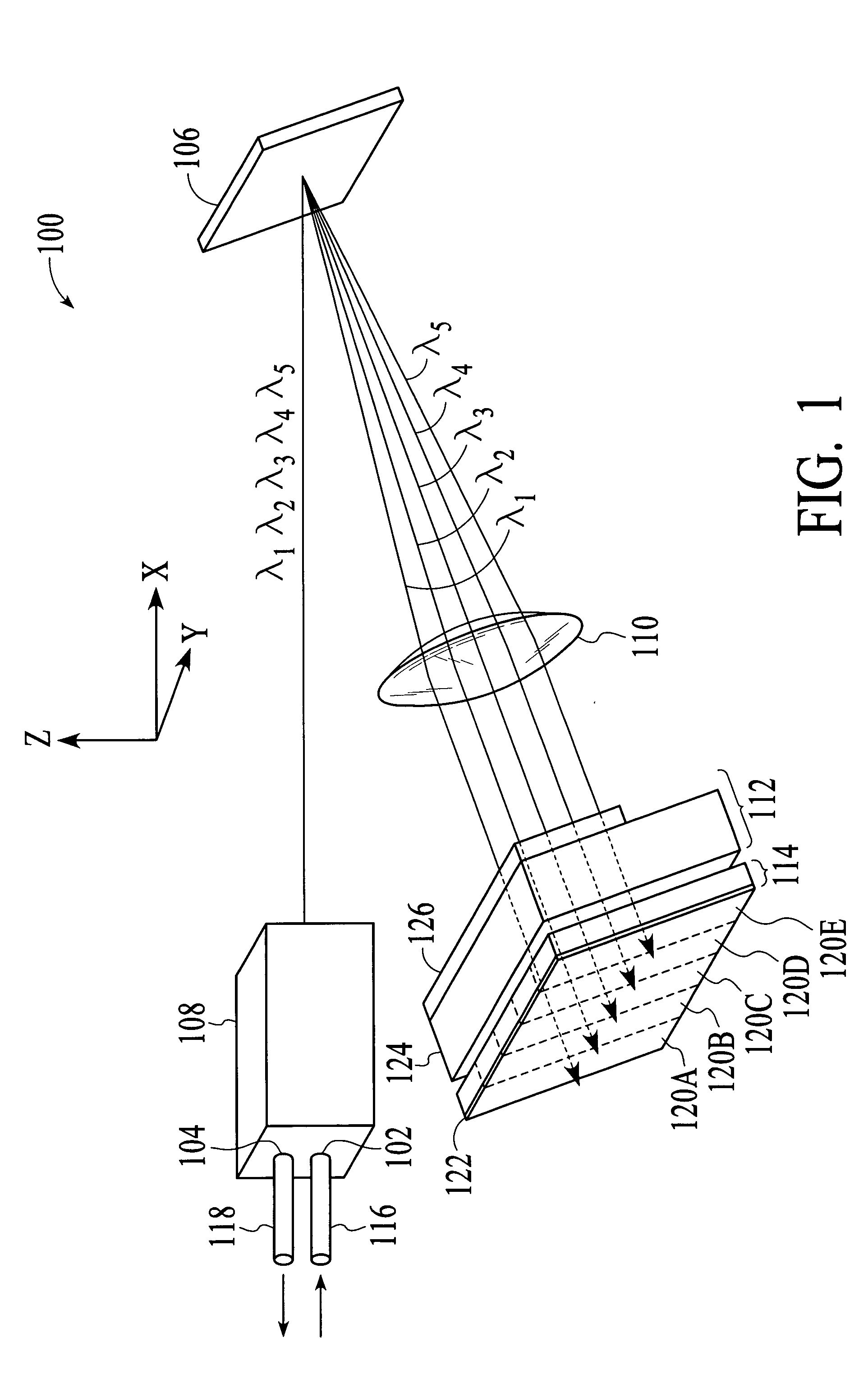
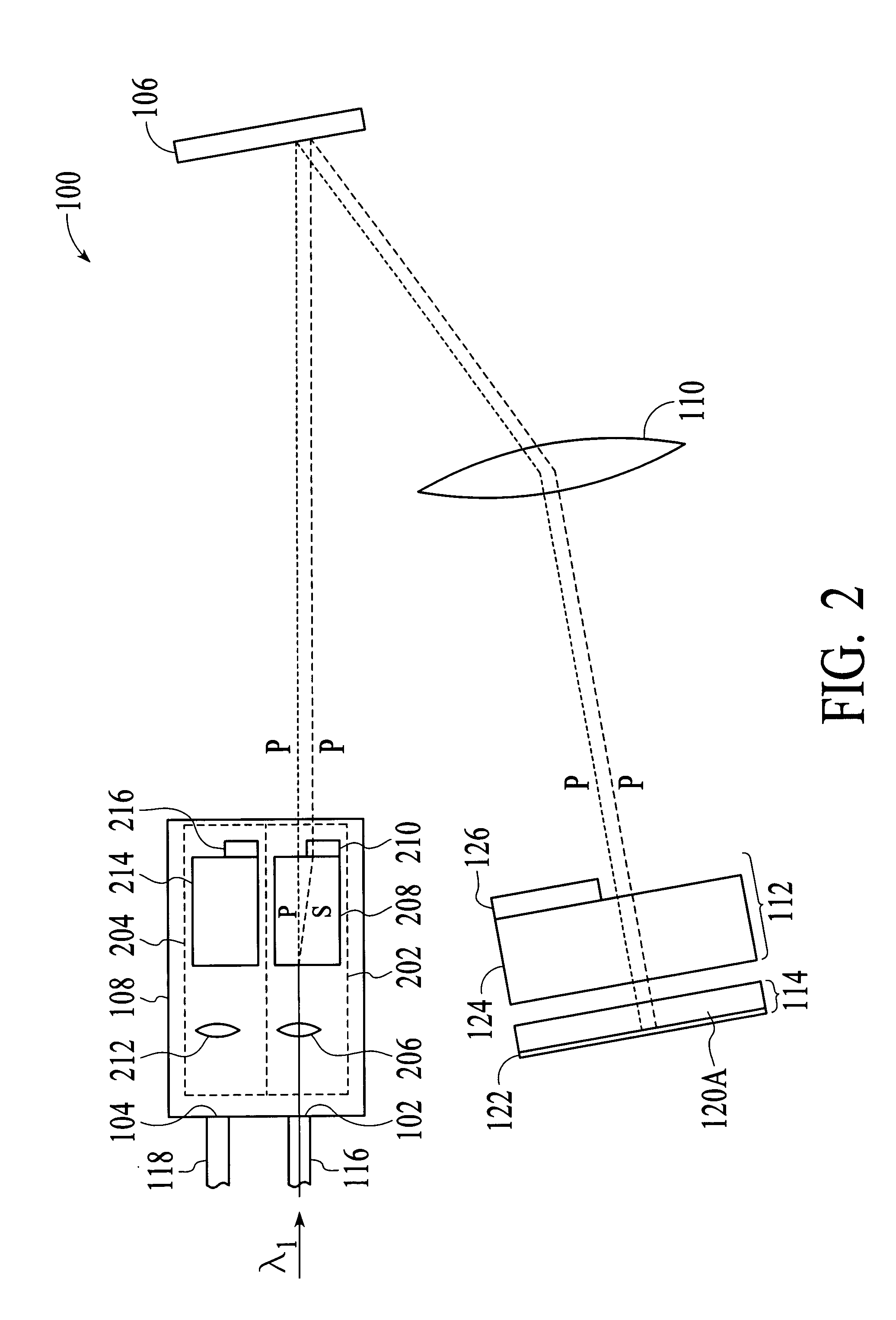
[0006] A wavelength selective switching device and method for selectively transmitting optical signals based on wavelength utilizes diffraction to spatially separate the optical signals of different wavelengths such that the optical signal of a selected wavelength can be selectively transmitted. The wavelength selective switching device selectively rotates the polarization components of the optical signals such that the polarization states of the polarization components are the same in both incoming and outgoing directions at the diffraction grating. Thus, a diffraction grating with a high grating line frequency (e.g. greater than 900 grating lines per mm for signals in the 1550 nm wavelength range) can be used for diffracting the polarization components of the optical signals in both the incoming and outgoing directions. The use of such a diffraction grating allows the size of the device to be reduced.

Problems solved by technology

However, diffraction gratings with high grating line frequency (e.g. greater than 900 grating lines per mm for optical signals in the 1550 nm wavelength range) are only efficient for one polarization state, and thus cannot be used in a wavelength selective switching device with a liquid crystal switching array in a conventional reflective configuration.

Method used


Image

  • Wavelength selective switching device and method for selectively transmitting optical signals based on wavelength
  • Wavelength selective switching device and method for selectively transmitting optical signals based on wavelength
  • Wavelength selective switching device and method for selectively transmitting optical signals based on wavelength

Examples


Embodiment Construction

[0019] With reference to FIG. 1, a perspective view of a wavelength selective switching device 100 in accordance with an embodiment of the invention is shown. The wavelength selective switching device 100 selectively transmits a single-wavelength optical signal of a wavelength division multiplexed (WDM) optical signal received at an input 102 of the device to the output 104 of the device, depending on the wavelength of the single-wavelength optical signal. In addition, the wavelength selective switching device 100 uses a diffraction grating 106 with a high grating line frequency (e.g. greater than 900 grating lines per mm for optical signals in the 1550 nm wavelength range). The use of such a diffraction grating allows the wavelength selective switching device 100 to provide more accessible wavelengths, i.e., channels, without significantly increasing the physical size of the device.

[0020] As shown in FIG. 1, the wavelength selective switching device 100 includes a front-end optics...


PUM

PropertyMeasurementUnit
wavelength rangeaaaaaaaaaa
grating line frequencyaaaaaaaaaa
optical propertyaaaaaaaaaa

Abstract

A wavelength selective switching device and method for selectively transmitting optical signals based on wavelength utilizes diffraction to spatially separate the optical signals of different wavelengths such that the optical signal of a selected wavelength can be selectively transmitted. The wavelength selective switching device selectively rotates the polarization components of the optical signals such that the polarization states of the polarization components are the same in both incoming and outgoing directions at the diffraction grating. Thus, a diffraction grating with a high grating line frequency (e.g. greater than 900 grating lines per mm for signals in the 1550 nm wavelength range) can be used for diffracting the polarization components of the optical signals in both the incoming and outgoing directions.

Description

FIELD OF THE INVENTION [0001] The invention relates generally to optical devices, and more particularly to an optical device and method for selectively transmitting optical signals based on wavelength. BACKGROUND OF THE INVENTION [0002] Wavelength selective switching devices are important components in optical communications systems. As an example, a wavelength selective switching device may be used to selectively transmit only optical signals of a selected wavelength, and thus, to block the other optical signals of different wavelengths. Such a wavelength selective switching device is commonly referred to as a blocking filter. [0003] Typically, a wavelength selective switching device includes two major functional parts, a demultiplexer and an active switching or attenuating element. The demultiplexer spatially separates the different wavelength optical signals, while the active element selectively routes the optical signals based on wavelength. For a high number of accessible wavel...

Claims


Application Information

Patent Timeline
Patent Type & Authority Applications(United States)
IPC IPC(8): G02F1/01H04Q11/00
CPCG02F1/31H04Q2011/0035H04Q2011/0026H04Q11/0005
Inventor HELBING, RENEHOKE, CHARLES D.NISHIMURA, KEN
Owner AVAGO TECH WIRELESS IP SINGAPORE PTE
Learn More