Parallel redundant power system and the control method for the same

a power system and control method technology, applied in power conversion systems, dc-ac conversion without reversal, electrical equipment, etc., can solve problems such as circuit complexity, load shortening, and possible serious economic loss, and achieve the effect of superior reliability

Inactive Publication Date: 2005-04-07
PHOENIXTEC POWER
View PDF3 Cites 101 Cited by
  • Summary
  • Abstract
  • Description
  • Claims
  • Application Information

AI Technical Summary

Benefits of technology

[0008] The main objective of the present invention is to provide a parallel power system capable of controlling current sharing. When the power system experiences abnormal situations such as the current surge, a non-linear load or a short circuit, the gain value of the controller is instantly adjusted. Moreover, the cross current is controlled by utilizing a concept of power balance while the output impedance is simultaneously considered without separating the cross current into two vectors, so that the power system possesses superior reliability.

Problems solved by technology

Especially in the present age where a breathtaking variety of electronic products are widely used, serious economic loss may possibly occur if a company loses critical data when the electricity supply is suddenly interrupted.
In the actual environment, the UPS may face many difficult problems, for example the fluctuation of the input voltage, thunderstorm interference, the sudden change of the load (the load may even short), and the continuous operation for twenty-four hours a day.
However, if the manufacturer intends to improve the reliability to be higher, not only will the circuit become more complex, but also the cost will also be greatly increased.
There is no doubt that the reliability of these inverters will be improved by implementation, however, most of the control means for the power supply system is accomplished by hardware, so the gain of the controllers is unable to be modified and thus the transient (dynamic) response of the power supply system is difficult to handle.
The method taught by the cited patent is so complex that a high reliability may not be obtained and the fabrication cost is increased to a non-commercially.
Furthermore, if the inverter is used as an adaptive inverter for the UPS, the cited patent does not take into account the input DC voltage of the inverter from the bus, and the influence generated while the inverter is coupled to any other module is also not considered either.
Once the synchronize signal experiences failure, the entire power system will breakdown.

Method used


Image

  • Parallel redundant power system and the control method for the same
  • Parallel redundant power system and the control method for the same
  • Parallel redundant power system and the control method for the same

Examples


Embodiment Construction

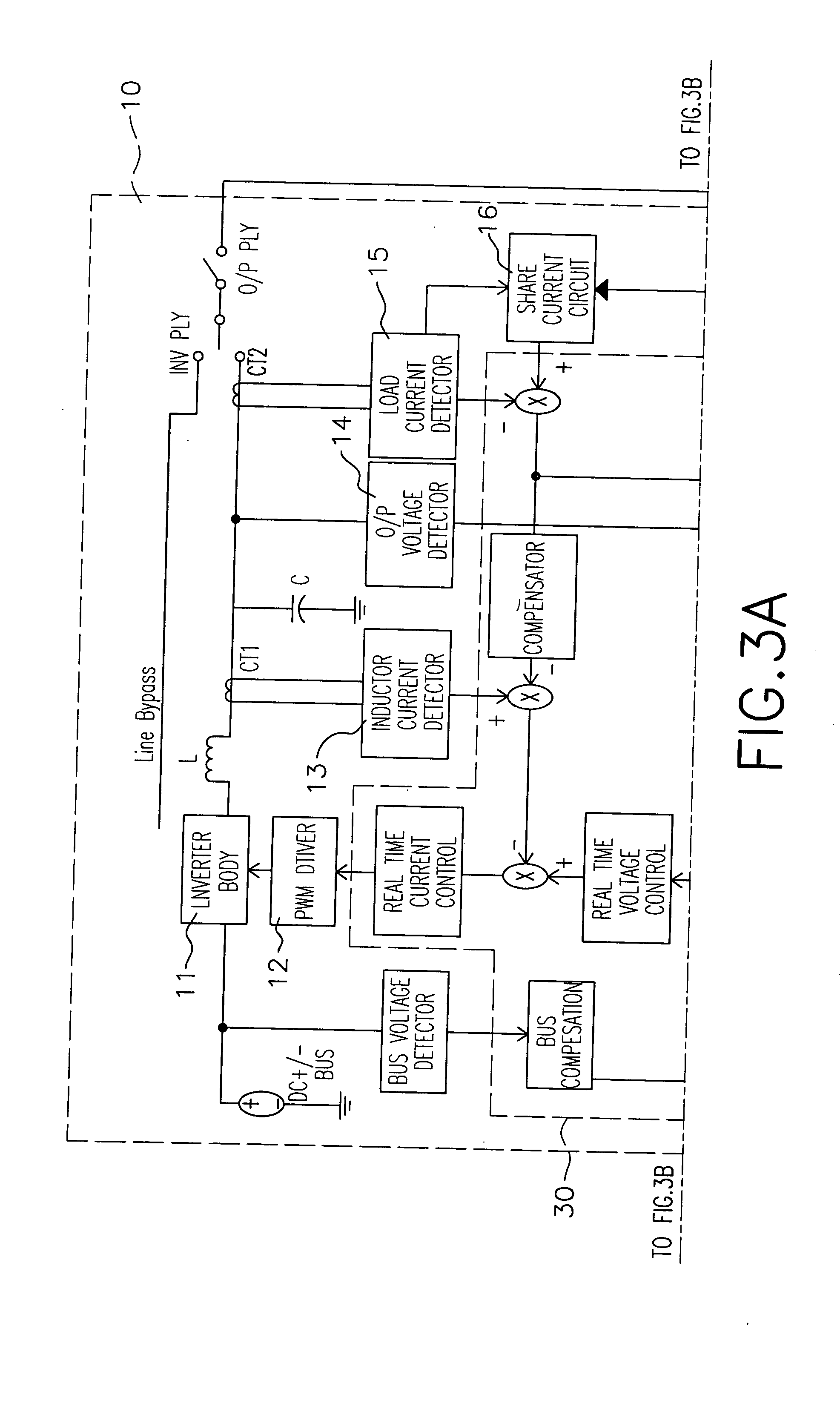
[0031] For a preferred embodiment of the present invention, a parallel (N+1) redundant power system utilizes a digital signal processor (DSP) as a controller applied to an on-line type UPS module, wherein an inverter of the UPS module is a half-bridge topology.

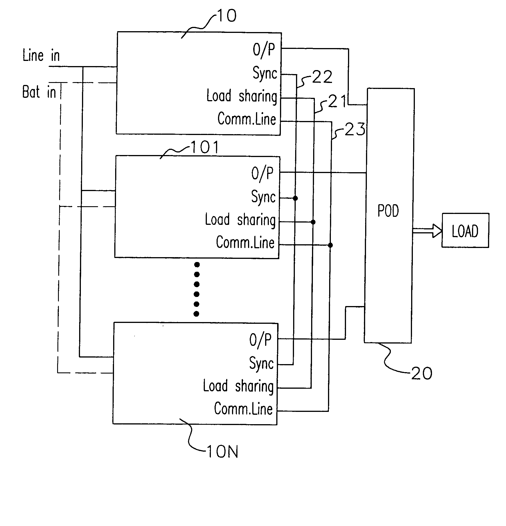
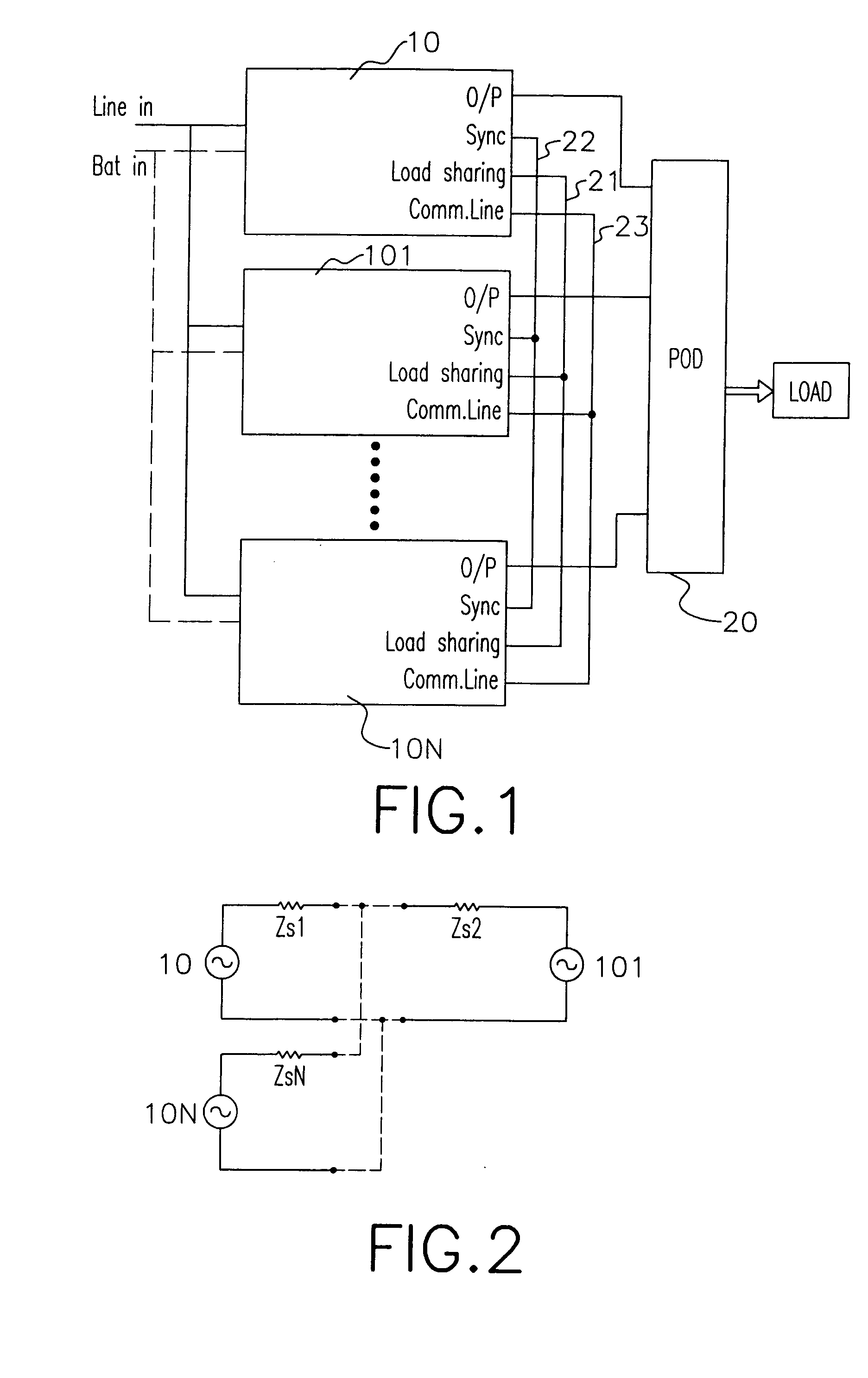
[0032] With reference to FIG. 1, the parallel redundant UPS system is composed of plural UPS modules (10)(101-10N) connected in parallel. If the output power of each UPS module (10)(101-10N) is high, all the UPS modules (10)(101-10N) are coupled through a power output distributor (POD)(20) to supply the composed power to the load. Otherwise, if the output power of each UPS module (10)(101-10N) is low, all the UPS modules (10)(101-10N) can coupled together via lines and then they collectively provide the power to the load without the use of the POD (20).

[0033] In order to perform a by-pass path (bypass function), all the UPS modules (10)(101-10N) are coupled to the AC input line voltage (Line in) in parallel. The power system...


PUM


Abstract

A power redundant power system and a method for controlling the power system are presented, wherein the power system is composed of at least one inverter for supplying AC power to a load through a bus, a phase lock system to synchronize all output voltages of the inverters and a current sharing circuit to properly distribute the load current among all inverters. Each inverter is controlled by an unbalanced power to limit the increase of its cross current. Moreover, the information related to DC bus voltage is further applied to control the inverters, whereby the cross current is mitigated and entire power system is operated steadily.

Description

BACKGROUND OF THE INVENTION [0001] 1. Field of the Invention [0002] The present invention is related to a parallel redundant power system and the control method for the same, and more particularly to a power system that utilizes an unbalanced power calculation and a cross current limitation technique to control the response of the inverter. [0003] 2. Description of Related Arts [0004] With the almost total dependence of modern societies on electricity for employment, living, communication and entertainment, any disruption to an electricity supply brings about a temporary halt to civilization as we know it. Especially in the present age where a breathtaking variety of electronic products are widely used, serious economic loss may possibly occur if a company loses critical data when the electricity supply is suddenly interrupted. [0005] To solve the above problem, the uninterruptible power supply (UPS) has been developed for providing a stable power supply. The most important objectiv...

Claims


Application Information

Patent Timeline
Patent Type & Authority Applications(United States)
IPC IPC(8): H02M7/48H02M7/493
CPCH02M7/493
Inventor LUO, HAN-SHENGTIAN, SHOU-LONGTSAI, CHIA-MING
Owner PHOENIXTEC POWER
Why Eureka
Try Eureka