Eureka AIR delivers breakthrough ideas for toughest innovation challenges, trusted by R&D personnel around the world.

Fixing device and image forming apparatus using the same

Inactive Publication Date: 2005-04-07
KONICA MINOLTA BUSINESS TECH INC
View PDF4 Cites 5 Cited by
  • Summary
  • Abstract
  • Description
  • Claims
  • Application Information

AI Technical Summary

Benefits of technology

Based on the invention described in structure 1, since there is no need to mount the heat source in the heating roller, the cored cylinder is not heated excessively, and thereby, prevented is deterioration of roller life due to the heat deterioration as well as the unglue which may result between the elastic layer and the cored cylinder. Further, since heating is not performed through the cored cylinder of the heating roller and the elastic layer, a fixing device featuring high heat conductivity and lower electric power consumption can be realized.
Based on the invention of structure 2, since the pressure roller is released from the heating roller when the recording material is not fed between them, prevented is permanent deformation of the elastic layer of the heating roller and the elastic layer of the pressure roller.
Based on the invention of structure 3, it is possible to provide the color image forming apparatus which can produce the color image of high quality on the front and back pages of the recording sheet, without any problem caused by deterioration of the elastic layer of the fixing device.

Problems solved by technology

However, when heat from the heat source in the cored cylinder is increased excessively, the elastic rubber layer is damaged by the heat, and the durability of the elastic rubber layer is deteriorated, whereby a problem results in that the elastic layer is unglued from the cored cylinder.
However, in both of these technologies disclosed in Patent Documents 1 and 2, since a pressure roller is a hard roller, though high image quality such as halftone is required, reproductivity of the image is not sufficient.
Further, in technology disclosed in Patent Document 3, a heat source is stored in a first fixing roller (heating roller), it takes long times to heat up the surface of the elastic layer to the level of fixing temperature, and if the heating capacity of the heat source is increased too large, the elastic layer made of a rubber is affected by the heat deterioration, which is a problem.

Method used


Image

  • Fixing device and image forming apparatus using the same
  • Fixing device and image forming apparatus using the same
  • Fixing device and image forming apparatus using the same

Examples


first embodiment

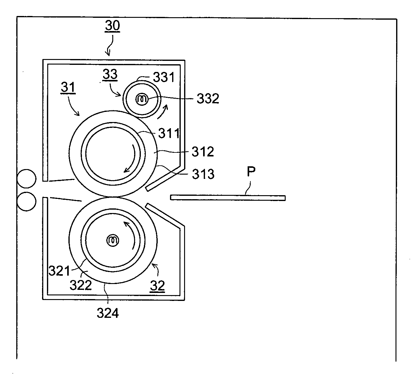
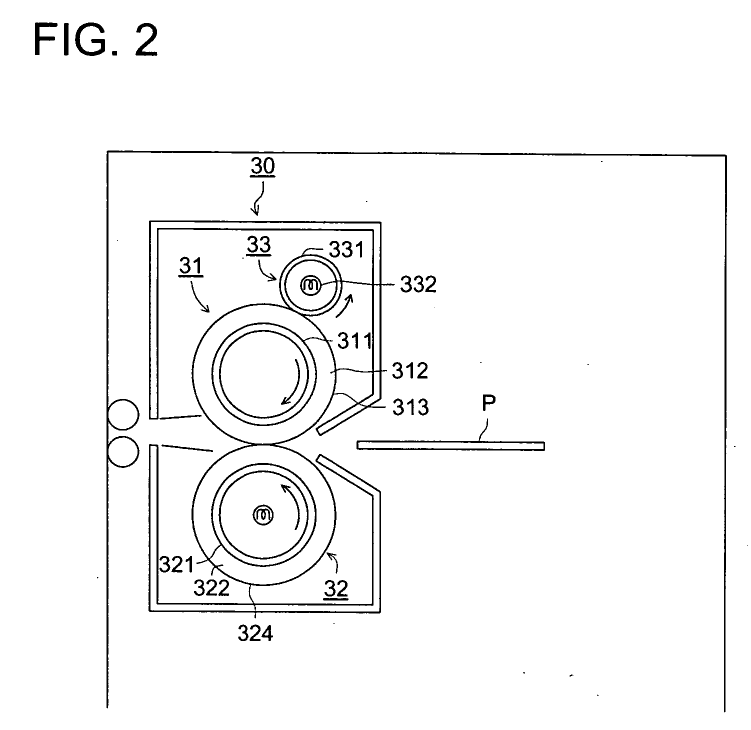
FIG. 2 is a cross sectional view showing the structure of the fixing device of the present invention.

In FIG. 2, fixing device 30 includes heating roller 31 excluding the heat source, pressure roller 32 being in pressure-contact with heating roller 31, and external heating roller 33 being also in pressure contact with heating roller 31.

Heating roller 31 is composed of cored cylinder 311 formed of a metal or a hard resin, elastic layer 312 formed of a rubber on the surface of cored cylinder 311, and fluorine resin layer 313 formed on the surface of elastic layer 312. Pressure roller 32 is composed of cored cylinder 321 formed of a metal or a hard resin, elastic layer 322 formed of a rubber on the surface of cored cylinder 321, and fluorine resin layer 323 (which is a toner releasing layer) formed on the surface of elastic layer 322.

External heating roller 33 is composed of roller member (which is a cored cylinder) 331 formed of aluminum or aluminum alloy, and heat source 332 whic...

second embodiment

FIG. 3 is a schematic view showing the structure of the fixing device of the present invention.

A position adjusting means of fixing device 30 shown in FIG. 3 is a method wherein pressure roller 32 is in pressure-contact at a the predetermined position. Both ends of rotating shaft 32A of pressure roller 32 is supported by pressing lever 32C one end of which is supported by pivoted supporting member 32B. The other end of pressing lever 32C is controlled by cam 32D to a predetermined pressing position. Cam 32D is driven by a driving source which is not illustrated. When the position of cam 32D is changed, the pressing point onto pressing lever 32C is consequently changed, and thereby, when recording sheet P is nipped, the center distance between heating roller 31 and pressure roller 32 is changed, and the nipping depth at fixing area N can be adjusted to a predetermined depth. Cam 32D is always in pressure-contact with pressing lever 32C by a spring.

FIG. 4 is a schematic view showing...


PUM


Abstract

A fixing device for fixing a recording sheet, including: a heating roller, a pressure roller, and an exterior heating roller; wherein the hardness of the elastic layer of the heating roller is less than that of the elastic layer of the pressure roller, and wherein the heat conductivity of the elastic layer of the heating roller is equal to or less than 0.2 W / m K, and the heat conductivity of the elastic layer of the pressure roller is equal to or greater than 0.4 W / m K.

Description

BACKGROUND OF THE INVENTION The present invention relates to a fixing device in which a recording material carrying a toner image is heated and is pressed between a heating roller and a pressure roller so that fixing is achieved, and an image forming apparatus including the same, and in particular, a fixing device wherein an external heating roller is provided which is in contact with the surface of the heating roller, and an image forming apparatus including the same. In an image recording apparatus employing an electrophotographic method, such as a copying machine, a facsimile device, and a laser printer, widely used is a fixing device wherein toner images are formed on a photoconductor, and after the toner images are transferred onto a recording sheet, the sheet is conveyed between a heating roller, which houses a heat source in a cored cylinder and generates heat through an elastic layer which is formed on the outer circumferential surface of the cored cylinder, and a pressure...

Claims


Application Information

Patent Timeline
IPC IPC(8): F16C13/00G03G15/20
CPCG03G15/2057
Inventor TANAKA, HAJIME
Owner KONICA MINOLTA BUSINESS TECH INC
Why Eureka
Eureka Blog
Learn More