

Non-white construction surface
- Summary
- Abstract
- Description
- Claims
- Application Information
AI Technical Summary
Benefits of technology
Problems solved by technology
Method used
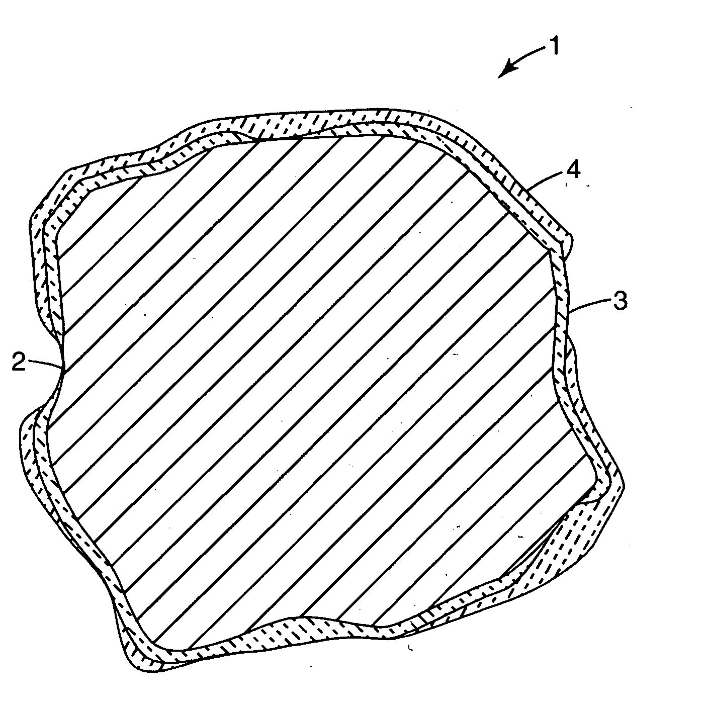
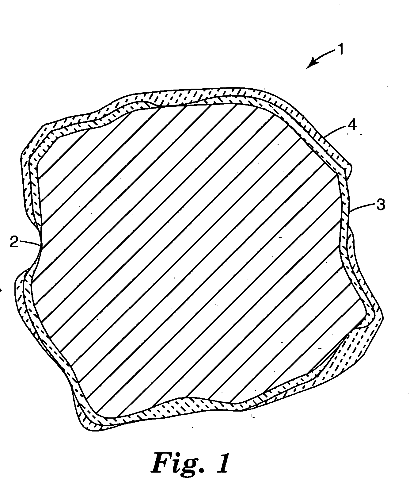
Image

Examples
examples
Materials
The following materials are used in the Examples: Sodium silicate solution (39.4% solids, 2.75 ratio SiO2 to Na2O) available from PQ Corp., Valley Forge, Pa. Kaolin clay (available as Snobrite from Unimin Corporation, New Canaan, Conn., typical composition: 45.5% SiO2, 38.0% Al2O3, 1.65% TiO2 and small amounts of Fe2O3, CaO, MgO, K2O and Na2O). Borax (Sodium Borate, 5 Mol, typical composition: 21.7% Na2O, 48.8% B2O3, and 29.5% H2O) available from U.S. Borax, Boron, Calif. Titanium dioxide (Tronox® CR-800, typical composition: 95% TiO2, alumina treated) available from the Kerr-McGee Corporation, Hamilton, Miss. Pigments (10411 Golden Yellow, 10241 Forest Green, V-3810 Red, V-9250 Bright Blue) available from Ferro Corporation, Cleveland, Ohio.
Grade #11 uncoated roofing granules (quartz lattite / dacite porphyry) (available from 3M Company, St. Paul, Minn.) specified by the following ranges (as per ASTM D451):
TABLE 1Nominal% RetainedU.S. Sieve No.OpeningMinimumMaximu...
examples 1-4
Examples 1-4 were produced by Granule Coating Method 1 and tested according to Test Methods 1 and 2. The results are summarized in Table 3.
TABLE 2The amounts listed are in parts by weight unless otherwise indicated.Example1234Kaolin clay22.5152020Sodium silicate solution65344040Water15151515CR 800 titanium dioxide8.75—30.810241 Forest Green—14—1.610411 Golden Yellow—1.24—V-13810 Red——0.2—V-9250 Bright Blue———0.6Borax311—Slurry Parts Per 100057.140.141.639.0Final Firing Temperature470° C.460° C.460° C.460° C.
TABLE 3Example1234Direct Solar Reflectance (%)30273430L*68.7555.9064.4062.63a*−0.46−8.625.96−5.32b*1.2712.4526.062.29Minimum Reflectivity20.53%29.07%23.83%20.21%(770-2500 nm)Summed Reflectance Value856012078106599686
PUM
| Property | Measurement | Unit |
|---|---|---|
| Fraction | aaaaa | aaaaa |
| Fraction | aaaaa | aaaaa |
| Nanoscale particle size | aaaaa | aaaaa |
Abstract
Description
Claims
Application Information