Harmonic force generator for an active vibration control system

a technology of active vibration control and generator, which is applied in the direction of mechanical vibration separation, shock absorbers, machines/engines, etc., can solve the problems of insufficient approach in a vehicle having a gearbox and unacceptable weight penalty, and achieve the effect of reducing weight and small siz

Inactive Publication Date: 2005-04-07
SIKORSKY AIRCRAFT CORP
View PDF30 Cites 58 Cited by
  • Summary
  • Abstract
  • Description
  • Claims
  • Application Information

AI Technical Summary

Problems solved by technology

Although effective, this approach is inadequate in a vehicle having a gearbox which is directly attached to the airframe i.e., without struts.
This system, although effective for direct gearbox mounting, requires a parasitic mass of considerable magnitude which may result in an unacceptable weight penalty.

Method used


Image

  • Harmonic force generator for an active vibration control system
  • Harmonic force generator for an active vibration control system
  • Harmonic force generator for an active vibration control system

Examples


Embodiment Construction

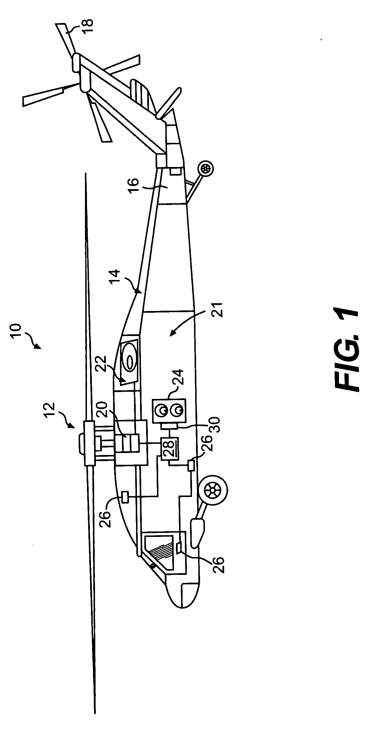
[0024]FIG. 1 schematically illustrates an aircraft 10 having a main rotor assembly 12. The aircraft 10 includes a fuselage 14 having an extending tail 16 which mounts an anti-torque rotor 18. Although a particular helicopter configuration is illustrated in the disclosed embodiment, other machines will also benefit from the present invention.

[0025] The main rotor assembly 12 is driven through a transmission (illustrated schematically at 20) by one or more engines 22. Vibrations from the rotating main rotor assembly 12, transmission 20, and the engines 22 are thus transmitted to the helicopter fuselage 14. This vibration transmission is particularly manifest in rigid gearbox mounted systems.

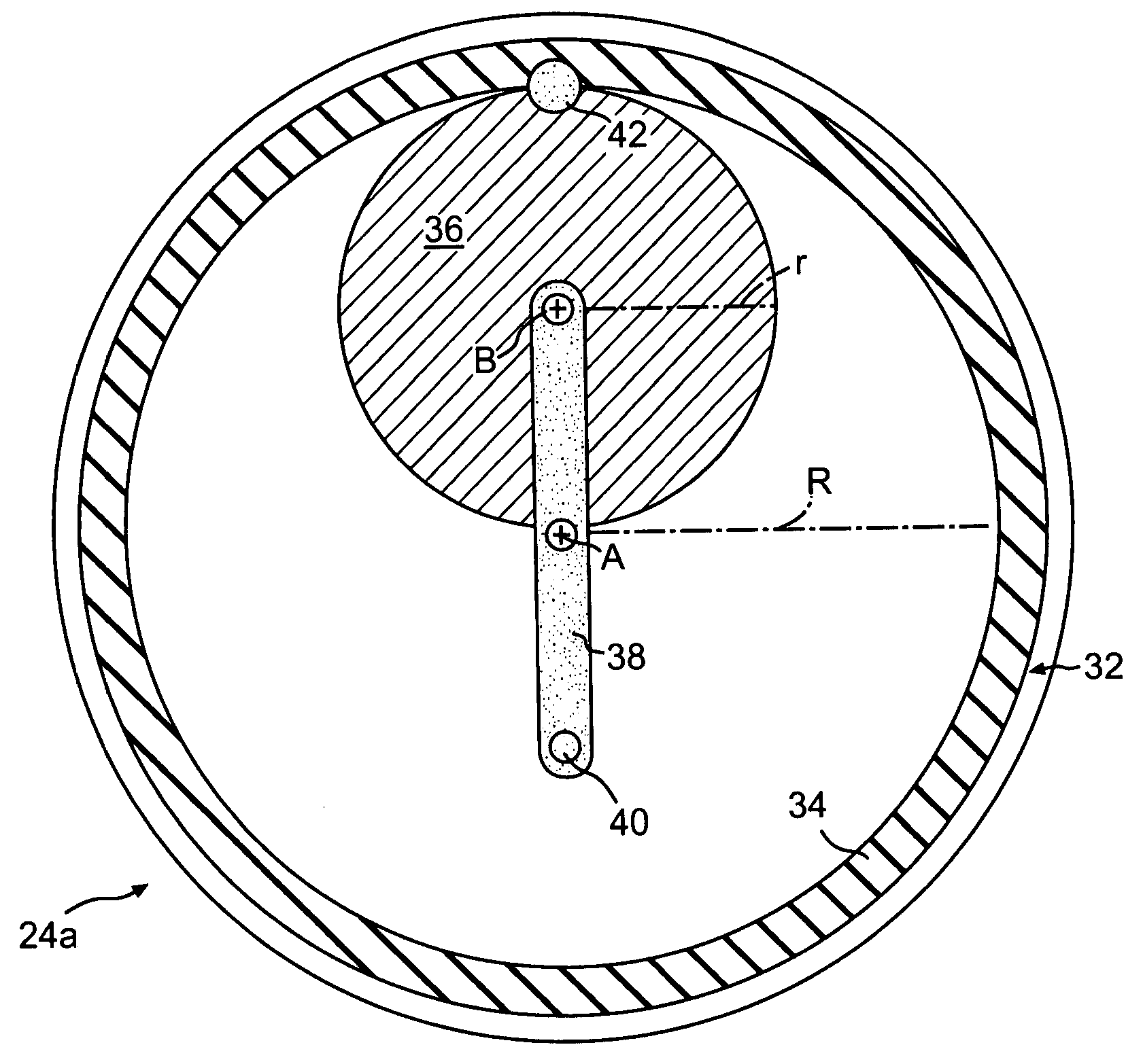
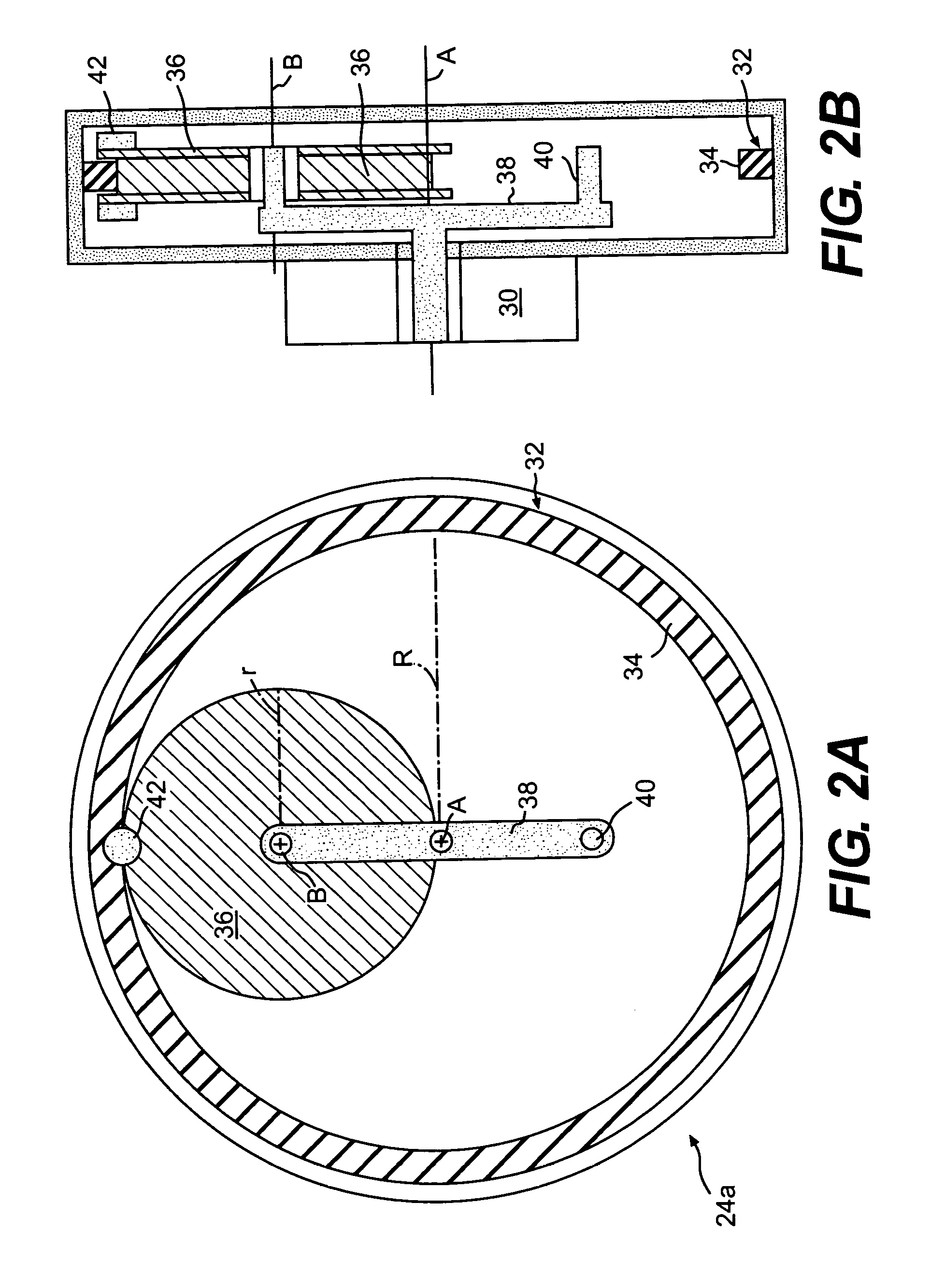
[0026] An active vibration control (AVC) system 21 includes one or more force generators 24 mounted within the fuselage 14, however, there are numerous locations within the aircraft 10 for locating the force generators 24. A plurality of sensors 26 are mounted at various locations and communicate...


PUM


Abstract

A force generator for an active vibration control (AVC) system provides a mass located upon an inner circular member which is movable within an outer circular member to simultaneously complete one revolution about its axis as it orbits within the outer circular member to compensate for sensed vibrations. A crank mounts the inner circular member and a counterweight. The crank is rotated by a prime mover such as an electric motor. The mass will therefore generate a sinusoidal inertial force in a straight line. Multiple systems are suitably arranged to be used in conjunction with one another to provide a wide range of inertial force outputs.

Description

BACKGROUND OF THE INVENTION [0001] The present invention relates to producing large, controllable, vibratory forces to compensate for sensed noise or vibrations, and more particularly to a force generator which is part of an active vibration control (AVC) system for an aircraft. [0002] The dominant source of vibration in a helicopter is that generated by the main rotor system at the blade passing frequency (rotation rate times the number of rotor blades). Forces and moments are transmitted usually through the transmission via fuselage attachments, to produce vibration in the fuselage. [0003] One conventional approach to reducing such vibration involves replacing a rigid gearbox mounting strut with a compliant strut and parallel hydraulic actuator. A controller commands the actuators such that the gearbox is selectively vibrated to produce inertial forces which minimize fuselage vibrations. Although effective, this approach is inadequate in a vehicle having a gearbox which is directl...

Claims


Application Information

Patent Timeline
Patent Type & Authority Applications(United States)
IPC IPC(8): B06B1/16B64C27/00F03G3/00F03H99/00F16F7/10F16F15/22
CPCB06B1/16B64C27/001B64C2027/004F03G3/00Y10T74/2109F16F7/1005F16F15/22Y10T74/2121F03H99/00
Inventor FREDERICKSON, KIRK CHARLES
Owner SIKORSKY AIRCRAFT CORP
Why Eureka
Try Eureka