Electronic endoscope

a technology of electronic endoscopes and endoscopes, which is applied in the field of electronic endoscopes, can solve the problems of complicated and expensive illumination devices, and achieve the effects of simple structure, long life and inexpensiveness

Inactive Publication Date: 2005-04-07
HENKE SASS WOLF
View PDF23 Cites 35 Cited by
  • Summary
  • Abstract
  • Description
  • Claims
  • Application Information

AI Technical Summary

Benefits of technology

[0004] According to the invention, this object is achieved in the afore-described electronic endoscope in that the illumination device comprises at least one light emitting diode as the light source. Nowadays, light emitting diodes are mass-produced articles which are extremely inexpensive and, on top of that, also have a very long life. This allows a simple structure of the electronic endoscope according to the invention, which additionally comprises an extremely inexpensive illumination device.

Problems solved by technology

This leads to a complicated and, thus, also expensive illumination device.

Method used


Image

  • Electronic endoscope
  • Electronic endoscope

Examples


Embodiment Construction

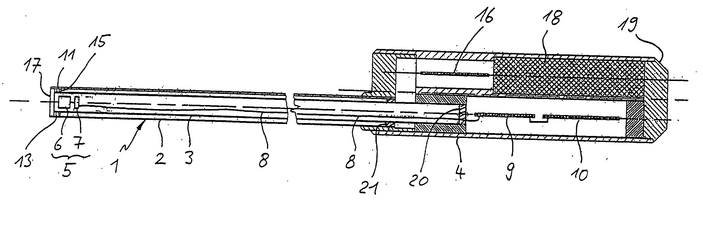
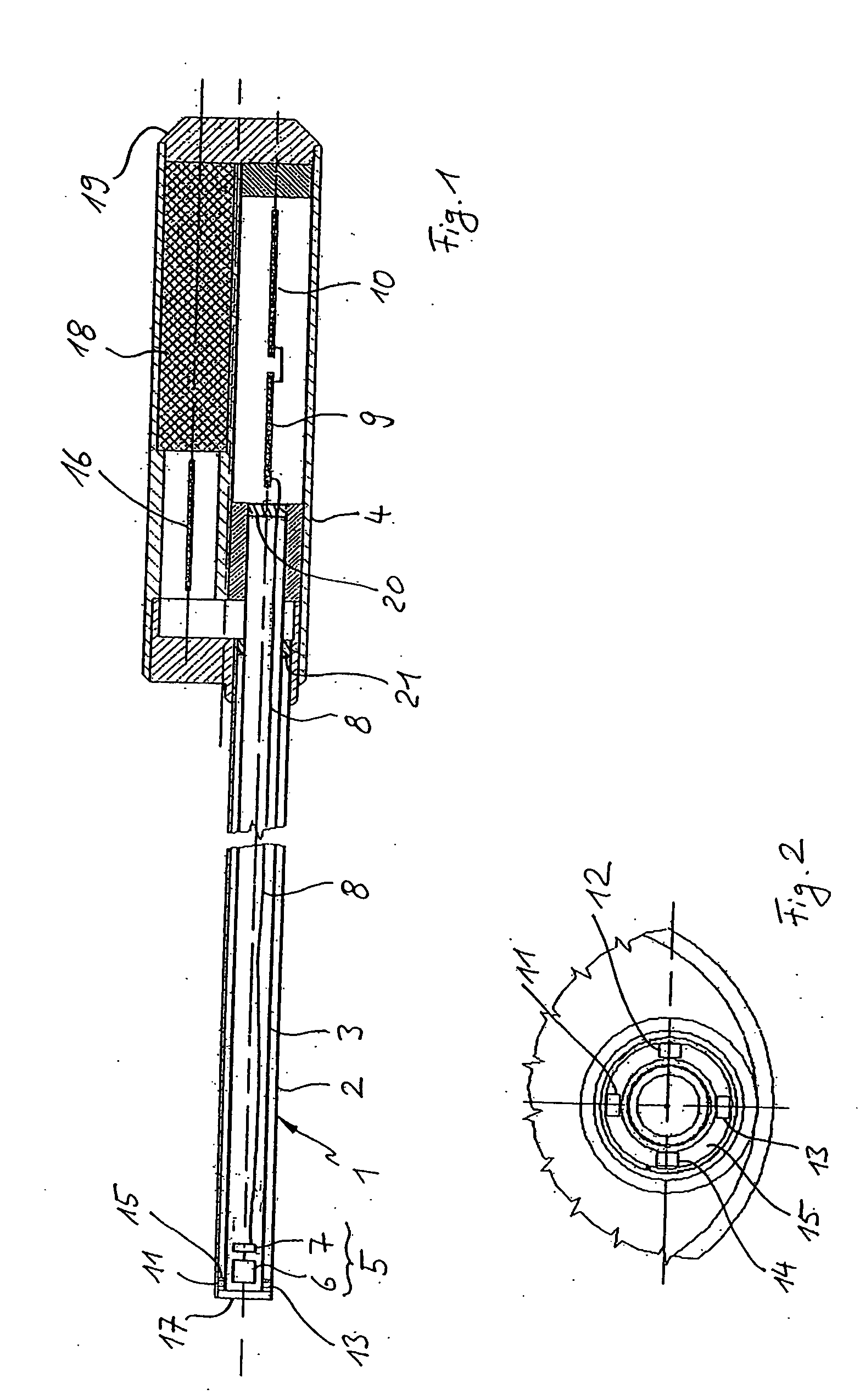
[0024] The autoclavable endoscope shown in the Figures is intended, in particular, for use in the medical field and comprises a shaft 1 having an outer tube 2 and an inner tube 3, which is arranged concentrically to the former. The proximal end of the shaft (and, thus, of both tubes 2 and 3) is connected to a handpiece 4 in a hermetically sealed manner, while in the inner tube 3 of the shaft 1, at the distal end of said shaft, an image-recording unit 5 is arranged, which comprises an objective 6 and an image sensor 7 arranged following the objective 6. The image-recording unit 5 is preferably securely connected to the shaft 1, so that the image-recording unit 5 is arranged in the shaft 1 in a stationary manner. However, the objective may certainly be provided as a zoom objective, for example. The image sensor 7 is preferably a CCD or CMOS image sensor.

[0025] The image sensor 7 is connected, via an electronic cable connection 8 schematically indicated in FIG. 1, with an image data p...


PUM


Abstract

An electronic endoscope is provided, comprising a shaft, an image-recording unit, which has an objective as well as, arranged following the objective, an image sensor for recording an object, and which is securely connected to the shaft at the distal end thereof, said endoscope further comprising a handpiece connected to the proximal end of the shaft, as well as an illumination device, connected to the shaft, for illuminating the object to be recorded, wherein the illumination device comprises at least one light emitting diode.

Description

[0001] The invention relates to an electronic endoscope comprising a shaft, an image-recording unit, which has an objective as well as, arranged following the objective, an image sensor for recording an object, and which is securely connected to the shaft at the distal end thereof, said endoscope further comprising a handpiece connected to the proximal end of the shaft, as well as an illumination device connected to the shaft for illuminating the object to be recorded. BACKGROUND OF THE INVENTION [0002] Such an electronic endoscope, which is described in DE 196 47 855 A1, for example, is employed, in particular, in the medical and technical fields. In many cases, the illumination device comprises a cold-light source whose light is coupled into a light conductor at the handpiece and is transmitted to the distal end of the shaft by the light conductor. This leads to a complicated and, thus, also expensive illumination device. [0003] In view thereof, it is an object of the invention to...

Claims


Application Information

Patent Timeline
Patent Type & Authority Applications(United States)
IPC IPC(8): A61B1/00A61B1/04A61B1/06
CPCA61B1/00165A61B1/0684A61B1/0607A61B1/04A61B1/00016A61B1/00032A61B1/00108A61B1/00142A61B1/05
Inventor SCHULZ, DIETERKIEHN, RALF
Owner HENKE SASS WOLF
Why Eureka
Try Eureka