Elevator, particularly for transporting persons

a technology for elevators and elevator cars, applied in the direction of elevators, motor/generator/converter stoppers, dynamo-electric converter control, etc., can solve the problems of insufficient power capability, redundant counterweights connected with elevator cars, and additional space requirements of drive pulleys and electric motors, and achieve favorable production costs and high power capability of drive motors.

Inactive Publication Date: 2005-04-14
INVENTIO AG
View PDF9 Cites 18 Cited by
  • Summary
  • Abstract
  • Description
  • Claims
  • Application Information

AI Technical Summary

Benefits of technology

[0006] The present invention is based on the object of developing an elevator of the kind stated above in the respect that a comparatively

Problems solved by technology

This indirect drive of the elevator car is associated with the disadvantage of an additional space requirement for the drive pulley and the electric motor.
Moreover, the provision of a linear motor makes a counterweight connected with the elevator car redundant.
An insufficient power capability and a manufacturing cos

Method used


Image

  • Elevator, particularly for transporting persons
  • Elevator, particularly for transporting persons
  • Elevator, particularly for transporting persons

Examples


first embodiment

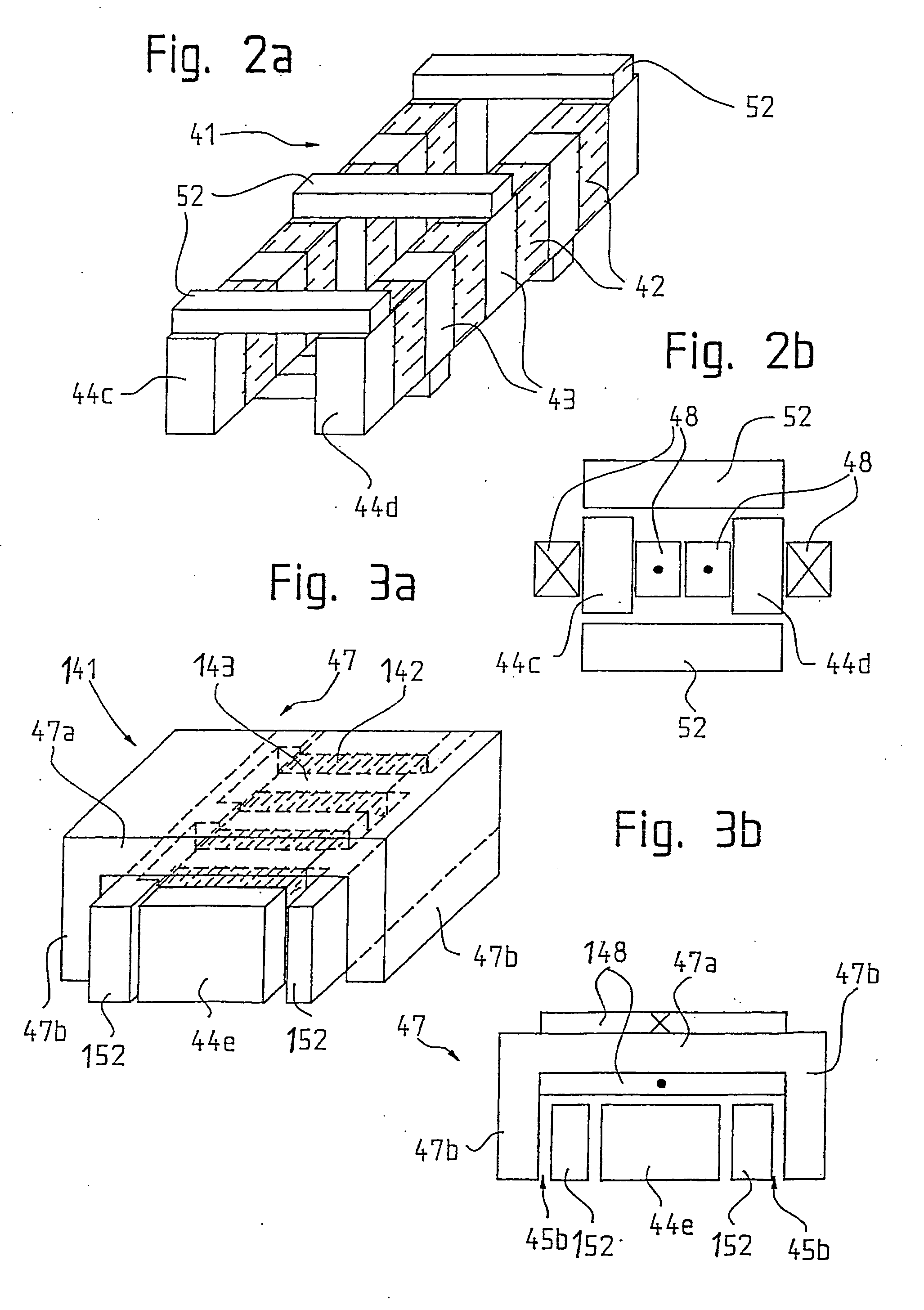
[0056] The first embodiment, which is shown in FIGS. 2a and 2b, of the excitation module 41 comprises the two collectors 44c, 44d which are constructed to be substantially I-shaped and arranged parallel to one another in the direction “X” of movement of the elevator car 20 and are each provided with a respective one of the excitation windings 48. With respect to a material-saving design, the feedback of the excitation winding 48, which usually consists of copper, in the case of arrangement of several of the excitation modules 41 can be utilized in order to excite an adjacent collector.

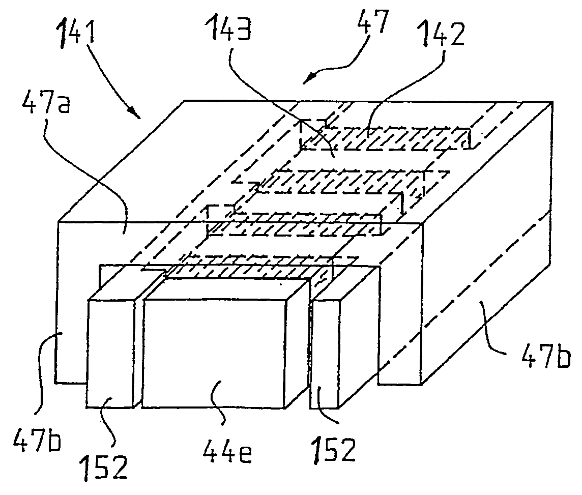
[0057] The second embodiment, which is shown in FIGS. 3a and 3b, of the excitation module 141 comprises a yoke 47 which surrounds the collector 44e at three sides and which is composed of a base plate 47a, which is provided with the excitation winding 148, and two limbs 47b. The limbs 47b are each spaced from the collector 44e by a respective intermediate space 45b and extend along two opposite sides o...

third embodiment

[0058] In a third embodiment, which is shown in FIGS. 4a and 4b, of the excitation module 241 is provided with the two collectors 44a, 44b which are constructed to be substantially U-shaped and face one another by their open sides and which are arranged to be spaced apart by an intermediate space 45a. The collectors 44a, 44b have limbs 46 which are respectively provided with the excitation windings 248 extending in the direction “X” of movement of the elevator car 20. Segments 252 of the rail 51 are arranged in the intermediate space 45a.

[0059] As is apparent from FIG. 4a, on supply of a three-phase current to the excitation winding 248 a magnetic flux M, which flows through the secondary part 50 and runs transversely to the direction “X” of movement of the elevator car 20, results. The magnet flux M of that kind also arises in the case of the forms of embodiment of the excitation modules 41, 141 according to FIGS. 2a through 3b. The first embodiment shown in FIGS. 2a and 2b differ...


PUM


Abstract

An elevator, particularly for transporting passengers, has an elevator car guided in an elevator shaft a direct drive motor. The drive motor includes an active primary part at the elevator car and a passive secondary part that is fixed in the elevator shaft and is spaced from the primary part by an air gap. In order to achieve a high power capability, the drive motor is configured as a transverse flux motor that moves the primary part linearly relative to the secondary part under the influence of an electromagnetic propulsive force. The secondary part has at least one rail made of a soft magnetic material and subdivided into a plurality of segments having a predetermined length. The segments are fixed to a wall of the elevator shaft by intermediate elements.

Description

BACKGROUND OF THE INVENTION [0001] The present invention relates to an elevator, particularly for transporting persons, which comprises an elevator shaft, an elevator car guided in the elevator shaft and a drive motor directly driving the elevator car. The drive motor is provided with an active primary part arranged at the elevator car and a passive secondary part arranged in stationary position in the elevator shaft and spaced from the primary part by an air gap. [0002] The elevator car of conventional elevators is usually moved up and down in the elevator shaft by means of wire cables that run over a drive pulley driven by an electric motor. This indirect drive of the elevator car is associated with the disadvantage of an additional space requirement for the drive pulley and the electric motor. [0003] In addition, elevators that are provided with a direct drive of the elevator car are known in the state of the art. Thus, the European patent document EP 0 785 162 A1 describes an el...

Claims


Application Information

Patent Timeline
IPC IPC(8): B66B9/02B60L13/10B66B9/08B66B11/04H02K41/03
CPCB60L13/10B60L2200/26B66B11/0407B66B11/04
Inventor DEPLAZES, ROMEOEVERTZ, JORGEILINGER, THOMAS
Owner INVENTIO AG
Why Eureka
Try Eureka