
Broad-band light source using a semiconductor optical amplifier

Inactive Publication Date: 2005-04-14
SAMSUNG ELECTRONICS CO LTD
View PDF12 Cites 21 Cited by
  • Summary
  • Abstract
  • Description
  • Claims
  • Application Information

AI Technical Summary

Benefits of technology

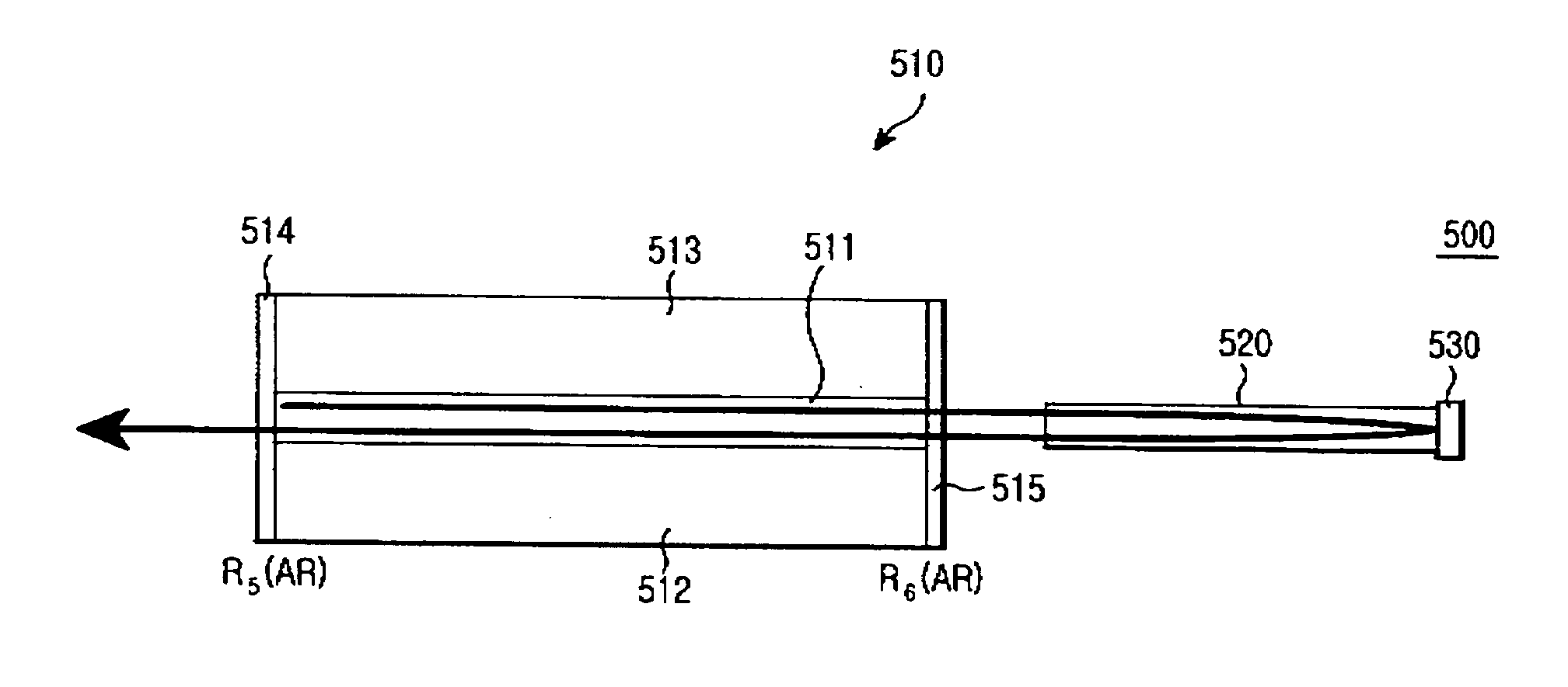
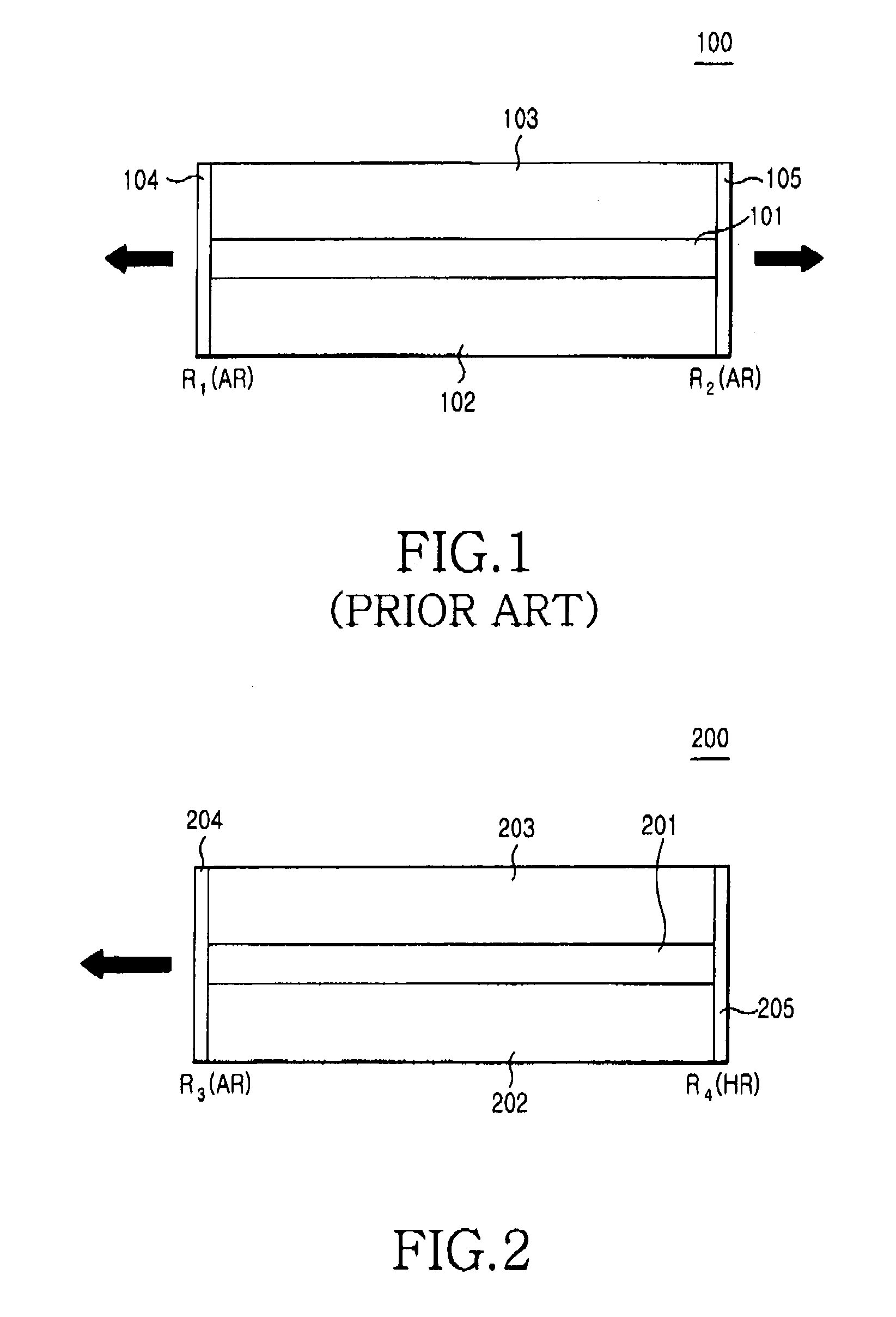
[0012] Therefore, the present invention has been made in view of the above problems and provides additional advantages, by providing a broad-band light source using a semiconductor optical amplifier, which maintains low gain ripple even at an area of high gain without a decrease in the reflectivity of an output terminal.
[0013] In accordance with the present invention, a broad-band light source includes a semiconductor optical amplifier having an active layer serving as a gain area, an under-cladding layer, an over-cladding layer, and antireflection layers formed at both ends of the active layer; and a reflector located at the outside of the semiconductor optical amplifier for reflecting the light outputted from the semiconductor optical amplifier so that the reflected light is inputted again to the active layer so as to minimize the gain ripple of the semiconductor optical amplifier.

Problems solved by technology

However, since a wavelength range of the light emitted from the EDFA is limited, the EDFA has a limited use as a broad-band light source.
Further, the EDFA is larger than most semiconductor devices available, thus it is difficult to reduce the production cost of the EDFA through a mass-production.

Method used


Image

  • Broad-band light source using a semiconductor optical amplifier
  • Broad-band light source using a semiconductor optical amplifier
  • Broad-band light source using a semiconductor optical amplifier

Examples


Embodiment Construction

[0023] Now, preferred embodiments of the present invention will be described in detail with reference to the annexed drawings. In the drawings, the same or similar elements are denoted by the same reference numerals even though they are depicted in different drawings. For the purposes of clarity and simplicity, a detailed description of known functions and configurations incorporated herein will be omitted as it may make the subject matter of the present invention unclear.

[0024]FIG. 5 is a schematic view of a broad-band light source using a semiconductor optical amplifier in accordance with one embodiment of the present invention.

[0025] As shown in FIG. 5, the broad-band light source 500 includes a semiconductor optical amplifier 510, a broad-band reflector 530 for reflecting light outputted from one end of the semiconductor optical amplifier 510, and an optical waveguide 520 for achieving an optical coupling between the semiconductor optical amplifier 510 and the broad-band refle...


PUM


Abstract

A broad-band light source using a semiconductor optical amplifier is provided. The broad-band light source includes the semiconductor optical amplifier including an active layer serving as a gain area, an under-cladding layer, an over-cladding layer, and antireflection layers formed at both ends of the active layer; and a reflector, located at the outside of the semiconductor optical amplifier, for reflecting light outputted from the semiconductor optical amplifier so that the reflected light is inputted back to the active layer so as to minimize gain ripple of the semiconductor optical amplifier.

Description

CLAIM OF PRIORITY [0001] This application claims priority to an application entitled “BROAD-BAND LIGHT SOURCE USING A SEMICONDUCTOR OPTICAL AMPLIFIER,” filed in the Korean Intellectual Property Office on Oct. 13, 2003 and assigned Serial No. 2003-71001, the contents of which are hereby incorporated herein by reference. BACKGROUND OF THE INVENTION [0002] 1. Field of the Invention [0003] The present invention relates to a broad-band light source utilizing a semiconductor optical amplifier. [0004] 2. Description of the Related Art [0005] Generally, broad-band light sources include a light emitting diode (LED), a super-luminescent diode (SLED), erbium-doped fiber amplifier (EDFA), etc. In particular, the EDFA widely used since it is capable of obtaining the polarization insensitive light of a high power stably. However, since a wavelength range of the light emitted from the EDFA is limited, the EDFA has a limited use as a broad-band light source. Further, the EDFA is larger than most se...

Claims


Application Information

Patent Timeline
IPC IPC(8): H01S5/50G02B6/10G02B6/42H01S3/00H01S5/00H01S5/028H01S5/10H01S5/14H04J14/02
CPCH01S5/028H01S2301/02H01S5/14H01S5/1039H01S5/50
Inventor KIM, SEUNG-WOOLEE, JEONG-SEOKHWANG, SEONG-TAEK
Owner SAMSUNG ELECTRONICS CO LTD
Learn More