Eureka AIR delivers breakthrough ideas for toughest innovation challenges, trusted by R&D personnel around the world.

Hash and route hardware with parallel routing scheme

a hardware and parallel routing technology, applied in the field of data communication, can solve the problems of significant processing capability and significant memory capacity, significant operational difficulties in coordinating the operation of multiprocessors, and difficult to share memory between nodes

Inactive Publication Date: 2005-04-14
AVAGO TECH INT SALES PTE LTD
View PDF12 Cites 91 Cited by
  • Summary
  • Abstract
  • Description
  • Claims
  • Application Information

AI Technical Summary

Benefits of technology

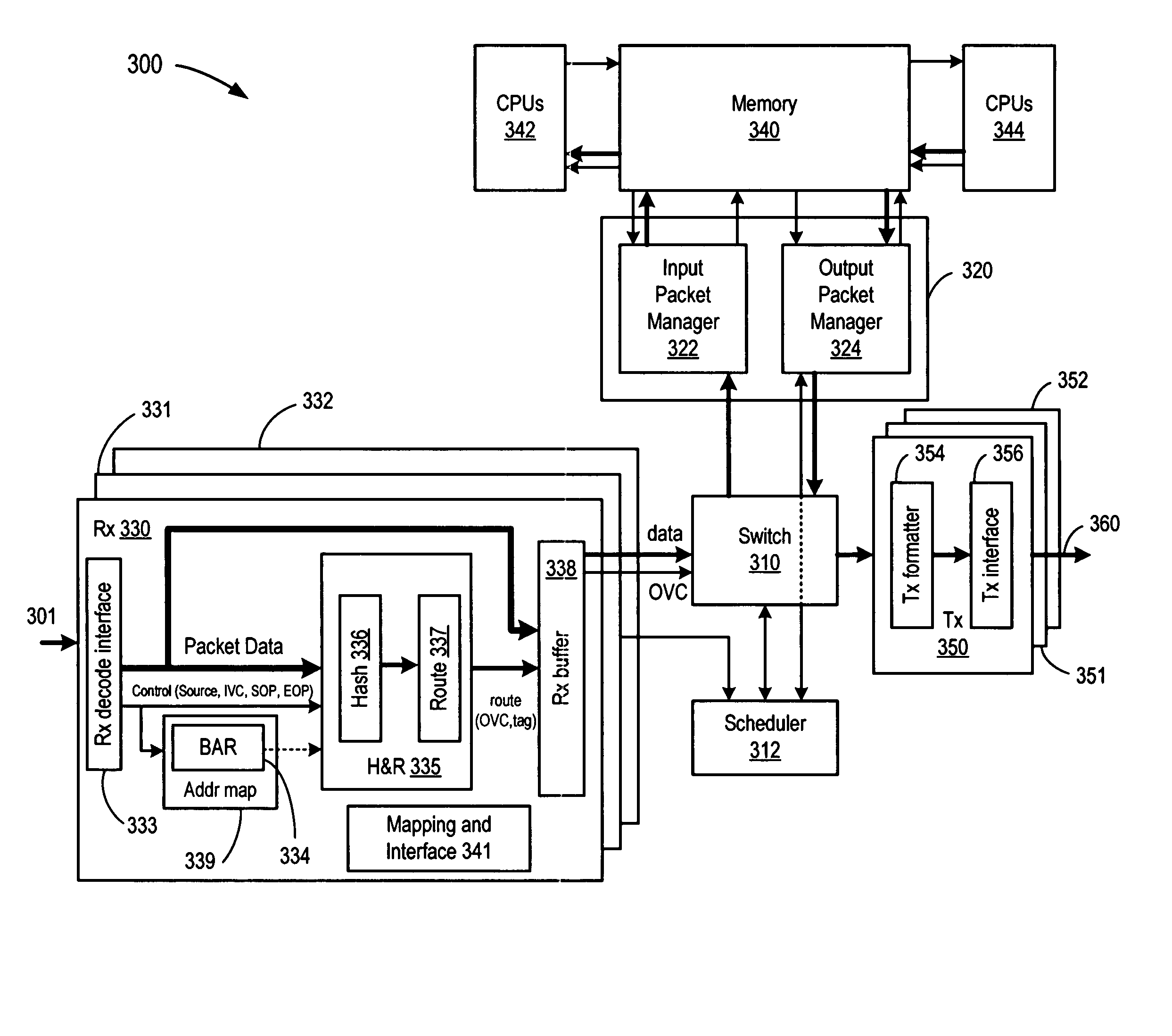
[0013] In a selected embodiment, a multiprocessor switching chip is provided with a receiver port and multiple destination modules, such as a packet manager input circuit and at least one transmit circuit integrated within the chip. A routing circuit coupled to the port receives packets is programmably configured to select a destination module for each packet by calculating a routing signal without requiring processor intervention. The routing circuit calculates the routing signal by using programmably selected control and data information extracted from the received packet as said received packet is being received. In one embodiment, the routing circuit includes a rule table that contains a plurality of independent rules that process data from the received packet in parallel as each packet is received to generate rule table outputs for each rule contained in the rule table. The routing circuit may also include a path table containing a plurality of paths that combine the rule table outputs from the rule table to generate a routing signal for the received packet. The routing signal may be used in a variety of ways to direct the received packet to a destination module. For example, the routing signal may be directly output as a routing result from the routing circuit to switch the received packet to a destination module identified by the routing result. The routing signal may also be used as an index to a routing table to output a routing result to switch the received packet to a destination module identified by the routing result. Alternatively or in addition, the routing signal may be used in combination with a hashed and/or extracted value to generate an index to a routing table to output a routing result to switch the received packet to a destination module identified by the hashed and/or extracted value and the routing result. The routing signal may also be a switch hop routing signal that is used to route t

Problems solved by technology

Of these devices that may be HT chained together, many require significant processing capability and significant memory capacity.
While a device or group of devices having a large amount of memory and significant processing resources may be capable of performing a large number of tasks, significant operational difficulties exist in coordinating the operation of multiprocessors.
Unfortunately, while the sharing of memory by processors within a single node is a fairly straightforward task, the sharing of memory between nodes is a daunting task.
Memory accesses between nodes are slow and severely degrade the performance of the installation.
An additional challenge for multiprocessor configurations is the routing of packet data within the multiprocessor devices.
In addition to consuming processor resources, the state machine approach can also impose significant buffer storage devices to hold the packet while the routing decision is being made, especially where a subsequent state relies on a prior packet bit.
Also, where multiple HT enabled nodes are connected through an external HT switch, the routing function can be impeded where the switch disregards packet information.

Method used


Image

  • Hash and route hardware with parallel routing scheme
  • Hash and route hardware with parallel routing scheme
  • Hash and route hardware with parallel routing scheme

Examples


Embodiment Construction

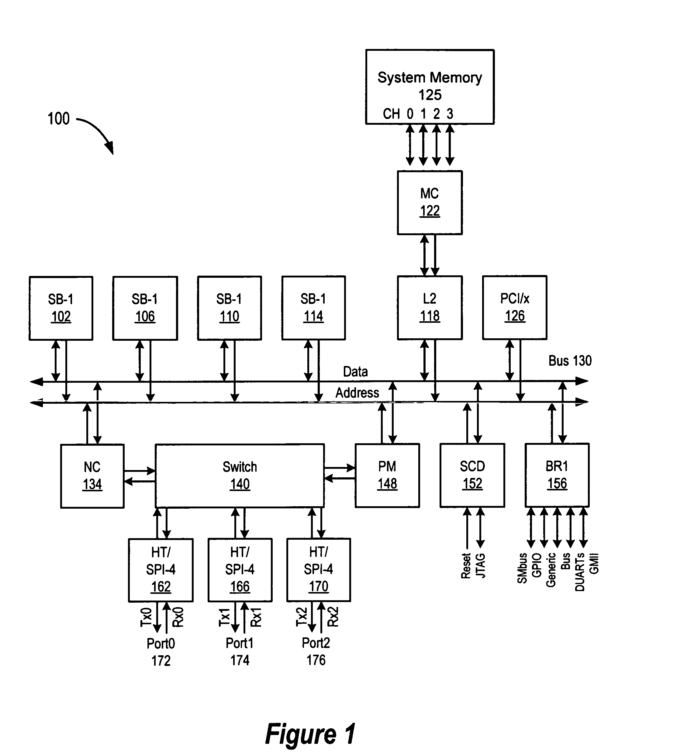
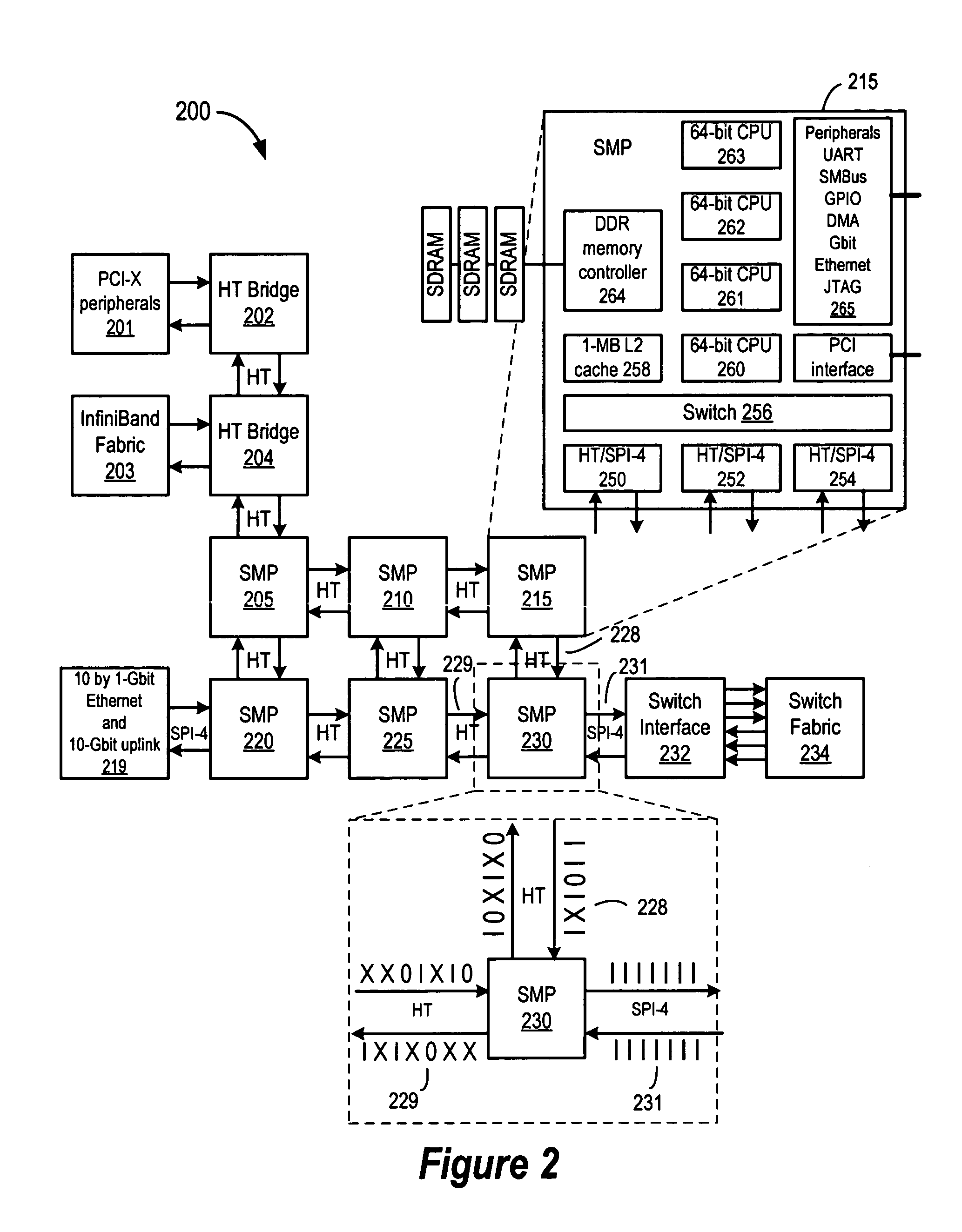
[0023] An apparatus and method in accordance with the present invention provide a system for routing incoming packets through a multiprocessor switching system-on-a-chip. A system level description of the operation of an embodiment of the multiprocessor switching system of the present invention is shown in FIG. 1 which depicts a schematic block diagram of a multiprocessor device 100 in accordance with the present invention. The multiprocessor device 100 may be an integrated circuit or it may be constructed from discrete components. The multiprocessor device 100 includes a plurality of processing units 102, 106, 110, 114, cache memory 118, memory controller 122, which interfaces with on and / or off-chip system memory, an internal bus 130, a node controller 134, a switching module 140, a packet manager 148, a system controller 152 and a plurality of configurable packet based interfaces 162, 166, 170, such as three flexible HyperTransport / SPI-4 Phase 2 links.

[0024] As shown in FIG. 1, ...


PUM


Abstract

A multiprocessor switching device substantially implemented on a single CMOS integrated circuit is described in connection with a parallel routing scheme for calculating routing information for incoming packets. Using the programmable hash and route routing scheme, a hash and route circuit can be programmed for a variety of applications, such as routing, flow-splitting or load balancing.

Description

RELATED APPLICATIONS [0001] This application is related to U.S. Provisional Patent Application Ser. No. 60 / 380,740, filed May 15, 2002; U.S. Provisional Patent Application Ser. No. 60 / 331,789, filed Nov. 20, 2001; U.S. Provisional Patent Application Ser. No. 60 / 344,713, filed Dec. 24, 2001; U.S. Provisional Patent Application Ser. No. 60 / 348,777, filed Jan. 14, 2002 and U.S. Provisional Patent Application Ser. No. 60 / 348,717, filed Jan. 14, 2002, each of which is incorporated herein by reference in its entirety.BACKGROUND OF THE INVENTION [0002] 1. Field of the Invention [0003] The present invention is directed in general to data communications. In one aspect, the present invention relates to a method and system for packet routing in high-speed data communication systems. [0004] 2. Related Art [0005] As is known, communication technologies that link electronic devices are many and varied, servicing communications via both physical media and wirelessly. Some communication technologie...

Claims


Application Information

Patent Timeline
IPC IPC(8): H04J1/16H04L12/56
CPCH04L45/00H04L45/54H04L49/109H04L45/745H04L45/60
Inventor MOLL, LAURENTSANO, BARTON J.PETERSEN, THOMAS ALBERT
Owner AVAGO TECH INT SALES PTE LTD
Why Eureka
Eureka Blog
Learn More