Expandable endovascular stent

a stent and endovascular technology, applied in the field of radially expandable endoprosthesis devices, can solve the problems of limiting the compactness of the stent in its compressed state for delivery, and reducing the amount of material needed, so as to reduce the amount of material required, facilitate delivery, and reduce the effect of material requirements

Inactive Publication Date: 2005-04-14
FENG JAMES Q +1
View PDF5 Cites 46 Cited by
  • Summary
  • Abstract
  • Description
  • Claims
  • Application Information

AI Technical Summary

Benefits of technology

The objective of the present invention is to provide an expandable endovascular stent configuration which minimizes the amount of material required for achieving adequate radial strength of the stent.
The further objective of the present invention is to provide an expandable endovascular stent which has substantial longitudinal flexibility and longitudinal dimensional stability during its radial expansion or contraction to facilitate delivery through tortuous body lumens and to minimize abrasion trauma on the vessel wall while retaining sufficient radial and hoop strength for supporting the vessel wall when implanted therein.
The objectives of the present invention is achieved by designing an expandable endovascular stent comprising a single walled tubular body of a biocompatible material having a plurality of annular segments, which are transverse to the longitudinal axis and have periodic wavelets with a plurality of alternating symmetric peaks and valleys consisting of an arc segment and a straight segment, with the said arc segment having a constant or nearly constant curvature and having the arc angle greater than 180 degrees when the stent is in compressed state, and with the said straight segment being tangentially connected to the said arc segment. The large radii of circular arc segments make it possible to distribute the local curvature variation over large amount of material during radial deformation of the stent, and therefore to eliminate the undesirable stress concentration, because the radial expansion and contraction of the stent correspond to changes in local curvature and the longitudinal projection of the peak-to-valley distance of those periodic wavelets in the annular segments.
In a preferred embodiment of the invention the expandable endovascular stent further comprises bridging elements connected to the annular segments with the connection points located at or near the stress-neutral points, where the said stress-neutral point being located midway between the symmetric peaks and valleys of the wavelets of the annular segments because the longitudinal projections of the middle points between the symmetric peaks and valleys of the wavelets of the annular segments do not change during radial deformation of the stent Another advantage of connecting the bridging elements with annular segments at those stress-neutral points is to reduce the susceptibility of restenosis development, as restenosis is known to occur more likely at the stress concentrated connection points.
According to the design principles disclosed by the present invention, the radial strength and the longitudinal flexibility of the stent can be determined independently by the design parameters for the annular segments and bridging elements, respectively, without compromising longitudinal dimension invariability of the stent.

Problems solved by technology

A major problem with the stent configurations disclosed by the prior art is that the amount of material needed to ensure its sufficient radial strength severely limits the compactness of the stent in its compressed state for delivery.
The difficulty in reducing the amount of material needed to ensure sufficient stent radial strength often comes from non-optimized stent configurations that lead to substantial stress concentration in some small zones as the stent deforms in the radial direction.
Localized stress concentration is also known to have a detrimental tendency to lead to stess-induced restenosis in the stented vessel.
Furthermore the interdependence and tradeoff between the radial and hoop strength and longitudinal flexibility, which also tend to cause considerable longitudinal contraction or shortening during radial expansion of the stent often leads to undesirable, if not serious, abrasion trauma on the vessel wall.

Method used


Image

  • Expandable endovascular stent
  • Expandable endovascular stent
  • Expandable endovascular stent

Examples


Embodiment Construction

For the purposes of promoting an understanding of the principles of the present invention, reference will now be made to the embodiment illustrated in the drawings and specific language will be used to describe the same. It will nevertheless be understood that no limitation of the scope of the invention is thereby intended, such alterations and further modifications in the illustrated device, and such further applications of the principles of the invention as illustrated herein being contemplated as would normally occur to one skilled in the art to which the invention relates.

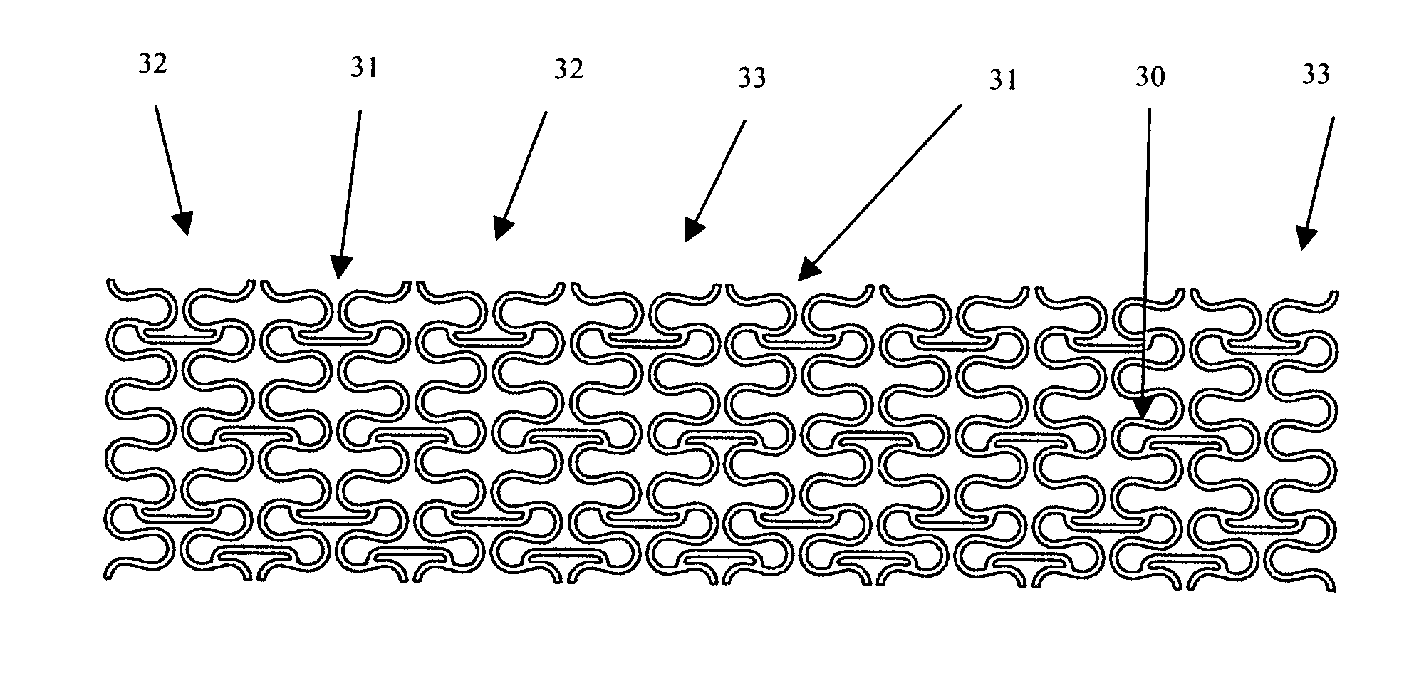
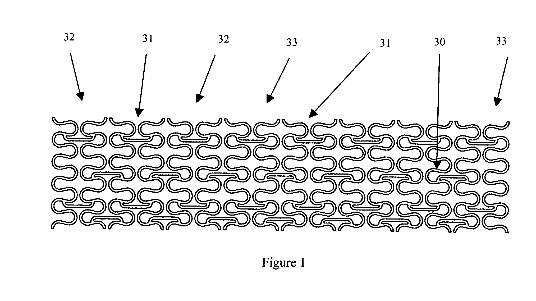
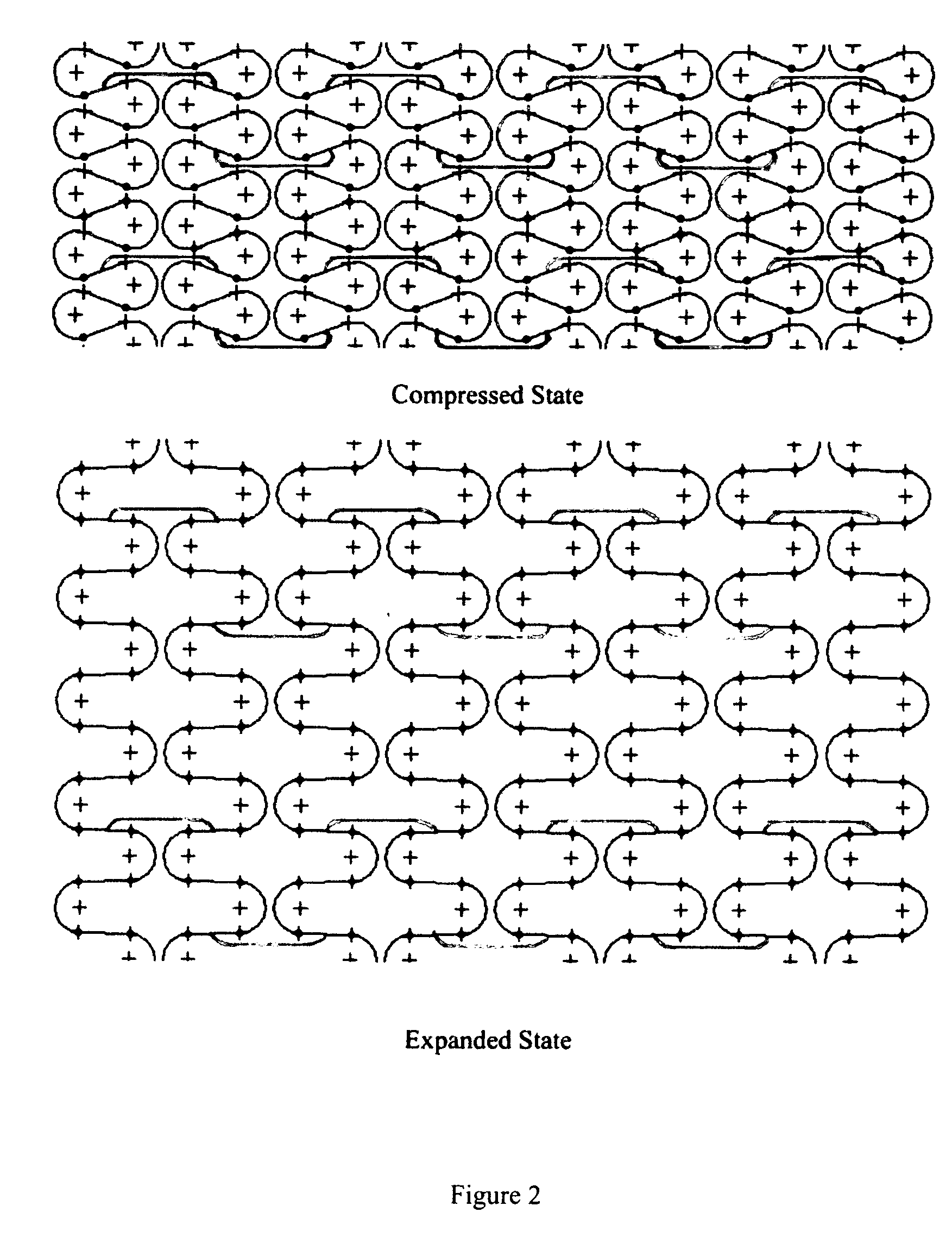
Illustrated in FIGS. 1-2 is a flat layout view of a tubular stent incorporating features of the present invention in its compressed and expanded states, respectively. The tubular stent generally comprises a plurality of annular segments 30, as referred to as “struts” hereafter, and a plurality of connecting elements 31, as referred to as “bridges” hereafter. Said struts are assembled in parallel along the le...


PUM


Abstract

Disclosed herein is a tubular endovascular stent comprising a plurality of annular segments connected by one or more bridging elements. Each annular segment takes forms of periodic wavelets with a plurality of alternating symmetric peaks and valleys, preferably consisting of circular arc segments of large radii connected tangentially with straight segments to minimize stress concentration when the stent undergoes radial deformation, transverse to the longitudinal axis of the stent. The points of connection between the bridging elements and adjacent annular segments are so designed that deformations of the bridging elements remain negligible as the stent deforms radially, namely, the longitudinal dimension of the stent does not vary during the radial expansion or contraction of the stent. Hence, the radial strength and the longitudinal flexibility of the stent made according to the principles disclosed by the present invention can be independently controlled by the design parameters for the annular segments and bridging elements, without compromising the longitudinal dimensional stability of the stent. Since stress concentration and deformation in the stent can lead to restenosis, stent made from the invention disclosed here can reduce the probability of restenosis.

Description

FIELD OF THE INVENTION The present invention relates to a radially expandable endoprosthesis device, and in particular to an expandable endovascular stent for implantation within a body vessel such as coronary or peripheral arteries or bile duct or urinary tract to widen a stenosis or open a blockage in the body vessel. BACKGROUND OF THE INVENTION Endovascular stenting is a method for inserting a prosthesis into a body vessel to widen a stenosis or to open a collapsed vessel wall, therefore to prevent restenosis or the wall from recollapsing into the vessel. The expandable endovascular stent is typically implanted intraluminally in its compressed or collapsed state using a catheter which is inserted at an easily accessible location and then advanced to the deployment site where the stent is to be radially expanded in situ from its compressed state. The stent may be self-expanded or expanded by inflation of a balloon on which the stent is mounted and carried on the catheter at the ...

Claims


Application Information

Patent Timeline
Patent Type & Authority Applications(United States)
IPC IPC(8): A61F2/06A61F2/90
CPCA61F2/91A61F2/915A61F2002/91525A61F2230/0013A61F2002/91558A61F2002/91583A61F2002/91541
Inventor FENG, JAMES Q.SUN, HUI
Owner FENG JAMES Q
Why Eureka
Try Eureka