
Delayed memory device

a memory device and delay technology, applied in the field of medical devices, can solve the problems of difficult to roll up the device on a catheter and then unfold it round the organ, and the device will start to contract, and achieve the effects of convenient manufacture, more rigid fixing, and convenient arrangemen

Active Publication Date: 2005-04-14
EDWARDS LIFESCIENCES AG
View PDF99 Cites 152 Cited by
  • Summary
  • Abstract
  • Description
  • Claims
  • Application Information

AI Technical Summary

Benefits of technology

[0013] Another advantage of the present invention is that there is no need for a stabilizing surgical instrument for keeping the device in said first state of shape during operation, since the shape is preserved by means of said delay means of the device.
[0014] Preferably, said delay means comprises a resorbable sheath being arranged to enclose said shape-changing member. This is advantageous since with the shape of a sheath the delay means is both easy to manufacture and easy to arrange on the shape-changing member.
[0015] In another preferred embodiment of the invention, said fixing means is arranged to expand against the wall of the vessel when first positioned therein. This expansion against the wall of the vessel initiates and contributes to the fixing of the ends of the device, thus providing said “temporary” fixing of the ends of the device within the vessel and enabling a more rigid fixing by ingrowth.
[0016] In yet another preferred embodiment of the invention, said fixing means is arranged to grow into the wall of the vessel, whereby said fixing of the ends of the device is reinforced. Hence, by taking advantage of the healing process in the tissue of the vessel wall, the fixing means can be fixed effectively. This can be facilitated by an expansion against the wall of the vessel as mentioned above.
[0017] In a preferred embodiment, said fixing means comprises hook means, by means of which said fixing of the ends of the device is reinforced. These hook means may be combined with the above-mentioned ingrowth of the fixing means in order to provide an even more secure fixation. The hook means may dig into the vessel wall and grow firmly fixed in the wall by the healing process.
[0018] In another preferred embodiment, said fixing means comprises a self-expandable stent at each end of the device.

Problems solved by technology

After a period of time after the surgical or percutaneous insertion, the device will start to contract as a result of the delay means being resorbed.
It is to be noted that if the contraction of the device would not have been delayed, it would have been very difficult to roll up the device on a catheter and then unfold it round the organ.

Method used


Image

  • Delayed memory device
  • Delayed memory device
  • Delayed memory device

Examples


Embodiment Construction

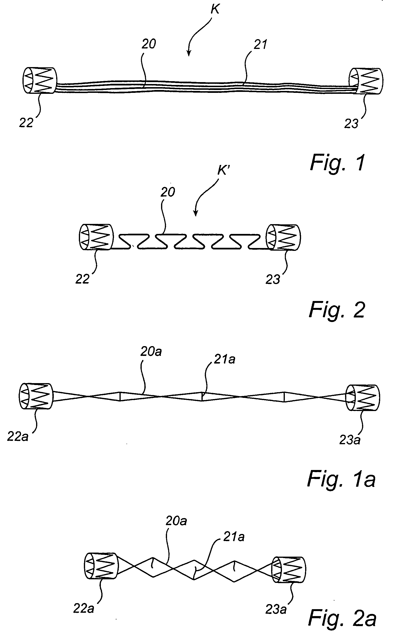
[0053]FIG. 1 shows one embodiment of a device according to the present invention for reshaping a cardiac valve, which may be used for treatment of mitral annulus dilatation.

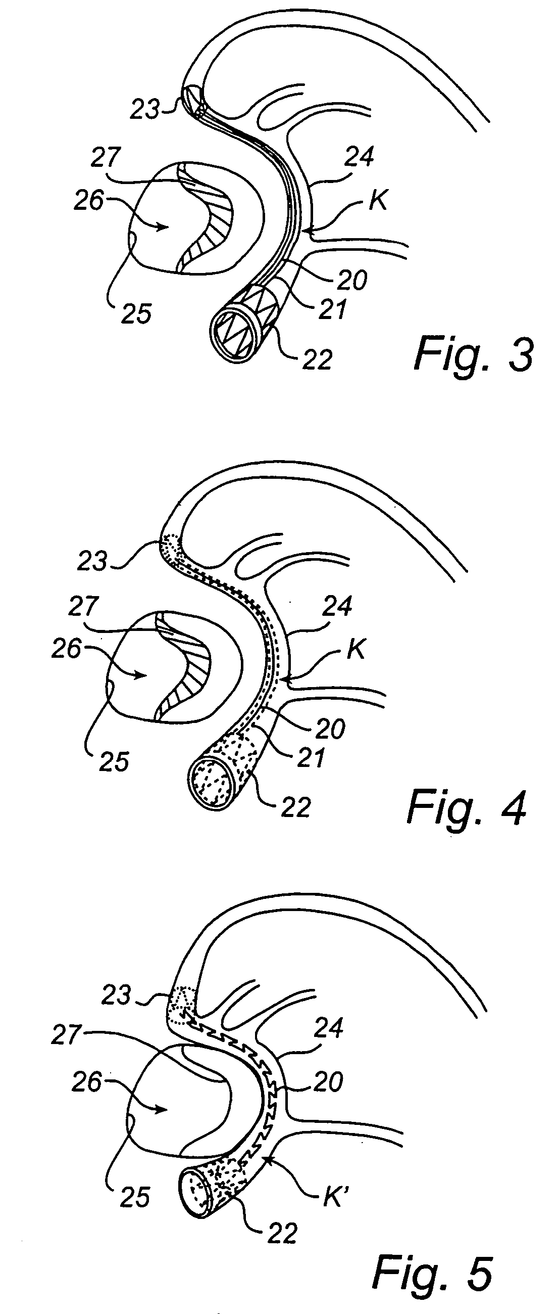
[0054] The device shown in FIG. 1, being in an elongate and non-activated state of shape K, comprises a shape-changing member in the form of a shape memory metal thread 20, a delay means in the form of a resorbable sheath 21 enclosing the shape memory metal thread 20 for holding it in a straightened state of shape, and preferably self-expandable stents 22 and 23 located at the opposite ends of the device.

[0055] The device may include one or more additional shape memory metal threads, e.g. if a stronger shortening force is desired.

[0056] The shape-changing member, in this embodiment in the form of the shape memory metal thread 20, may consist of or at least include Nitinol, or some other similar material which has a memory of an original shape as illustrated in FIG. 2, and can be temporarily forced into another...


PUM

PropertyMeasurementUnit
temperaturesaaaaaaaaaa
temperatureaaaaaaaaaa
distanceaaaaaaaaaa

Abstract

A device for reshaping a cardiac valve (26), which is elongate and has such dimensions as to be insertable into a cardiac vessel (24). The device has two states, in a first state (K) of which the device has a shape that is adaptable to the shape of the vessel (24), and to the second state (k′) of which the device is transferable from said first state (K). Further, the device comprises a fixing means (22,23;22a,23a) for fixing the ends of the device within the vessel (24), when the device is first positioned therein, a shape-changing member (20;20a) for transferring the device to the second state (K′) by reshaping it, and a delay means (21;21a) for delaying said reshaping until the fixing of the ends of the device has been reinforced by keeping said device in said first state (K) until the delay means (21;21a) is resorbed.

Description

TECHNICAL FIELD OF THE INVENTION [0001] The present invention relates to a medical device and a method for reshaping a cardiac valve. BACKGROUND OF THE INVENTION [0002] At present the treatment of mitral annulus dilatation and other mitral insufficiencies consists of either repair or mitral valve replacements. Both methods require open-heart surgery, by the use of total cardiopulmonary by-pass, aortic cross-clamping and cardioplegic arrest. To certain groups of patients, open-heart surgery is particularly hazardous and therefore a less invasive method for repair of mitral insufficiency is desired. [0003] Such a less invasive method is proposed in U.S. Pat. No. 6,210,432, which describes a method for treatment of mitral insufficiency without the need for cardiopulmonary by-pass and opening of the chest and heart. The method uses a device comprising an elongate body having such dimensions as to be insertable into the coronary sinus, which is a vein that substantially encircles the mit...

Claims


Application Information

Patent Timeline
Patent Type & Authority Applications(United States)
IPC IPC(8): A61F2/02A61F2/04A61F2/07A61F2/24A61F2/26A61F2/82A61F2/848
CPCA61F2/07A61F2/2451A61F2/2481A61F2/26A61F2210/0004A61F2002/072A61F2002/826A61F2002/828A61F2002/8483A61F2002/043
Inventor SOLEM, JAN OTTOKIMBLAD, PER OLAOEPEN, RANDOLF VONQUINT, BODOSEIBOLD, GERDMICHLITSCH, KENNETH JHA, SUK-WOOECKERT, KARL-LUDWIGJOERGENSEN, IBNIELSEN, STEVAN
Owner EDWARDS LIFESCIENCES AG
Learn More