Axially tapered and bilayer microchannels for evaporative coolling devices

a cooling device and evaporative technology, applied in the direction of power cables, cables, lighting and heating apparatus, etc., can solve the problems of greater viscosity friction, greater frictional resistance, and slower liquid transport through the wick ra

Active Publication Date: 2005-04-21
SANDIA NAT LAB
View PDF9 Cites 40 Cited by
  • Summary
  • Abstract
  • Description
  • Claims
  • Application Information

AI Technical Summary

Problems solved by technology

However, smaller pores result in greater frictional resistance and, hence, slower rates of liquid transport through the wick.
However, the triangular shape provides only half the cross-sectional area of a rectangular channel, the viscous friction is greater and, in addition, deep triangular cross sections cannot be readily produced using lithographic processes that have been so successful in mass production of semiconductor devices.
Multiple x-ray exposures at different angles to the mask could be used to produce triangular channels, but not without added complexity and loss of precision.
Although amenable to LIGA fabrication, straight rectangular microchannels have one notable disadvantage.

Method used


Image

  • Axially tapered and bilayer microchannels for evaporative coolling devices
  • Axially tapered and bilayer microchannels for evaporative coolling devices
  • Axially tapered and bilayer microchannels for evaporative coolling devices

Examples


Embodiment Construction

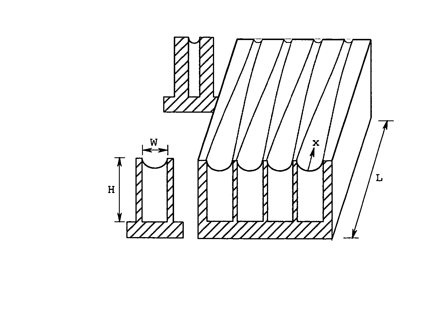
[0036] The simplest embodiment of this invention is an axially tapered microchannel formed into the body of a thermally conductive substrate member and having a flow cross-section that narrows in width along the intended flow path, as illustrated in FIGS. 4A through 4C. Such channels have no dead zone; they can be fabricated by lithographic processes such as LIGA, and they generally perform much better than prior art triangular grooves or straight rectangular channels. Through mathematical modeling it is shown here that the maximum sustainable heat flux for a tapered channel may exceed that of a comparable triangular groove by a factor of three to six. Tapered channels, such as those shown in FIG. 4A, also provide much more robust performance than straight rectangular channels by a three to four fold increase in their ability to overcome opposing gravitational forces. FIGS. 4B and 4C illustrate cross-sectional views of a representative channel at opposite ends of its length. When ap...


PUM


Abstract

The invention consists of an evaporative cooling device comprising one or more microchannels whose cross section is axially reduced to control the maximum capillary pressure differential between liquid and vapor phases. In one embodiment, the evaporation channels have a rectangular cross section that is reduced in width along a flow path. In another embodiment, channels of fixed width are patterned with an array of microfabricated post-like features such that the feature size and spacing are gradually reduced along the flow path. Other embodiments incorporate bilayer channels consisting of an upper cover plate having a pattern of slots or holes of axially decreasing size and a lower fluid flow layer having channel widths substantially greater than the characteristic microscale dimensions of the patterned cover plate. The small dimensions of the cover plate holes afford large capillary pressure differentials while the larger dimensions of the lower region reduce viscous flow resistance.

Description

STATEMENT OF GOVERNMENT INTEREST [0001] This invention was made with Government support under government contract no. DE-AC04-94AL85000 awarded by the U.S. Department of Energy to Sandia Corporation. The Government has certain rights in the invention, including a paid-up license and the right, in limited circumstances, to require the owner of any patent issuing in this invention to license others on reasonable terms.BACKGROUND OF THE INVENTION [0002] Evaporative cooling devices such as heat pipes and capillary pumped loops utilize capillary suction to draw liquid into the evaporation region. This capillary suction results from the pressure differential across the phase interface between a liquid and vapor. According to the Laplace-Young relation, the interfacial pressure difference is proportional to the surface tension and is inversely proportional to the radius of curvature of the interface. Further, since the pressure within the liquid is generally less than that in the adjacent ...

Claims


Application Information

Patent Timeline
Patent Type & Authority Applications(United States)
IPC IPC(8): F28D15/04
CPCF28D15/043F28F2260/02F28D15/046
Inventor NILSON, ROBERTGRIFFITHS, STEWART
Owner SANDIA NAT LAB
Why Eureka
Try Eureka