
Paper machine belt

a technology of paper machine and process belt, which is applied in the field of paper machine process belt, can solve the problems of paper sheet misalignment, paper sheet damage, and serious problems for papermakers

Inactive Publication Date: 2005-04-21
VOTH FABRICS PATENT GMBH
View PDF17 Cites 18 Cited by
  • Summary
  • Abstract
  • Description
  • Claims
  • Application Information

AI Technical Summary

Benefits of technology

[0010] For example, surprisingly, the provision of a similar mass of polymeric material on either side, i.e. face of the cd supporting layer, which gives the cross-machine strength and rigidity for the belt, results in a balancing effect insofar as the anticipated differential thermal shrinkage properties of the polymeric layers are concerned, so as to yield a belt with no edge curl. Different polymeric materials having different shrinkages may be used in combination, so that further to exposure to thermal energy, the shrinkage forces are balanced, eliminating edge curl.
[0015] It was found that this quasi-nonwoven cd supporting layer embedded between the layers of thermoplastic polymer, further to heat treatment and calendering, results in a laminated product with much improved macro-level pressure uniformity, due to the fact that there was far less chance of sheet marking, as is typical of substrates containing woven substrates with pronounced warp knuckles.
[0016] In addition, the belt preferably includes a machine direction (md) supporting layer to be needled on the roll side of the structure, to provide strength and md stability. This md supporting layer may be in the form of a woven, knitted or molded perforated membrane, for example of the type described in EP 0285376. However, this supporting fabric ideally includes an array of strong, stable, spirally wound, machine direction yarns. Layers of fibrous batt can also be needled in order to hold the yarns in position and to provide a coherent structure. The provision of additional batt on the roll side can also offer better wear resistance. In a preferred embodiment, the machine roll side layer is made up of spirally wound, machine direction, 0.2. mm / 2 ply / 3 cabled, polyamide yarns, with approximately 7 to 12 yarns / cm. There is approximately 50-800 g / m2 of polyamide batt fiber in the range of 3 to 67 dtex needled thereon. This whole layer preferably has a weight in-the range from 450 to 480 g / m2.
[0017] The spirally wound layer of md yarns with batt needled thereon is the preferred supporting substrate for a number of reasons. Firstly, marking due to cd / md yarn cross-over knuckles, as exist in woven substrates, is substantially eliminated.
[0031] Further to the needling process, the entire structure is then exposed to sufficient thermal energy to cause the lower melt point, thermoplastic, polymeric film to melt. This melted polymer bonds the structure together, embedding the cd supporting layer and part of the batt in a matrix of molten polymer and forms a very smooth and well defined impermeable surface., which is resistant to de-lamination. The belt is then smoothed with a cold polished cylinder. There is no need to grind the finished product, which is advantageous because this is extremely difficult to achieve in the case of low melt polymeric elastomers.
[0037] 5) further thermoplastic film or films, wherein the mass of thermoplastic material of layer (1) is preferably substantially the same as that in layer (5) to minimize edge-curl. Such an arrangement helps prevent batt loss and assists with ease of cleaning.

Problems solved by technology

When the web breaks the paper machine must be shut down and consequently this constitutes a serious problem to the papermaker.
In severe cases this can lead to the belt folding over which would, at the very least, mark the roller and cause misalignment and damage to the paper sheet.
For example, polyurethane film has a much greater shrinkage than the yarns of a woven structure and so when a film layer attached to a woven base cloth is partially melted, on cooling, it exerts a contractive force on the base structure, resulting in curling.

Method used


Image

  • Paper machine belt
  • Paper machine belt

Examples


Embodiment Construction

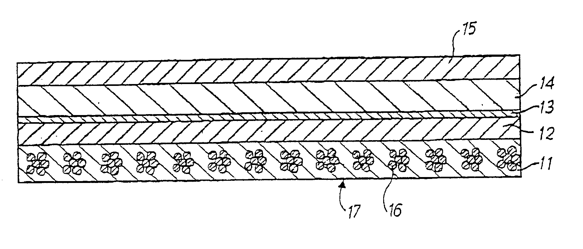
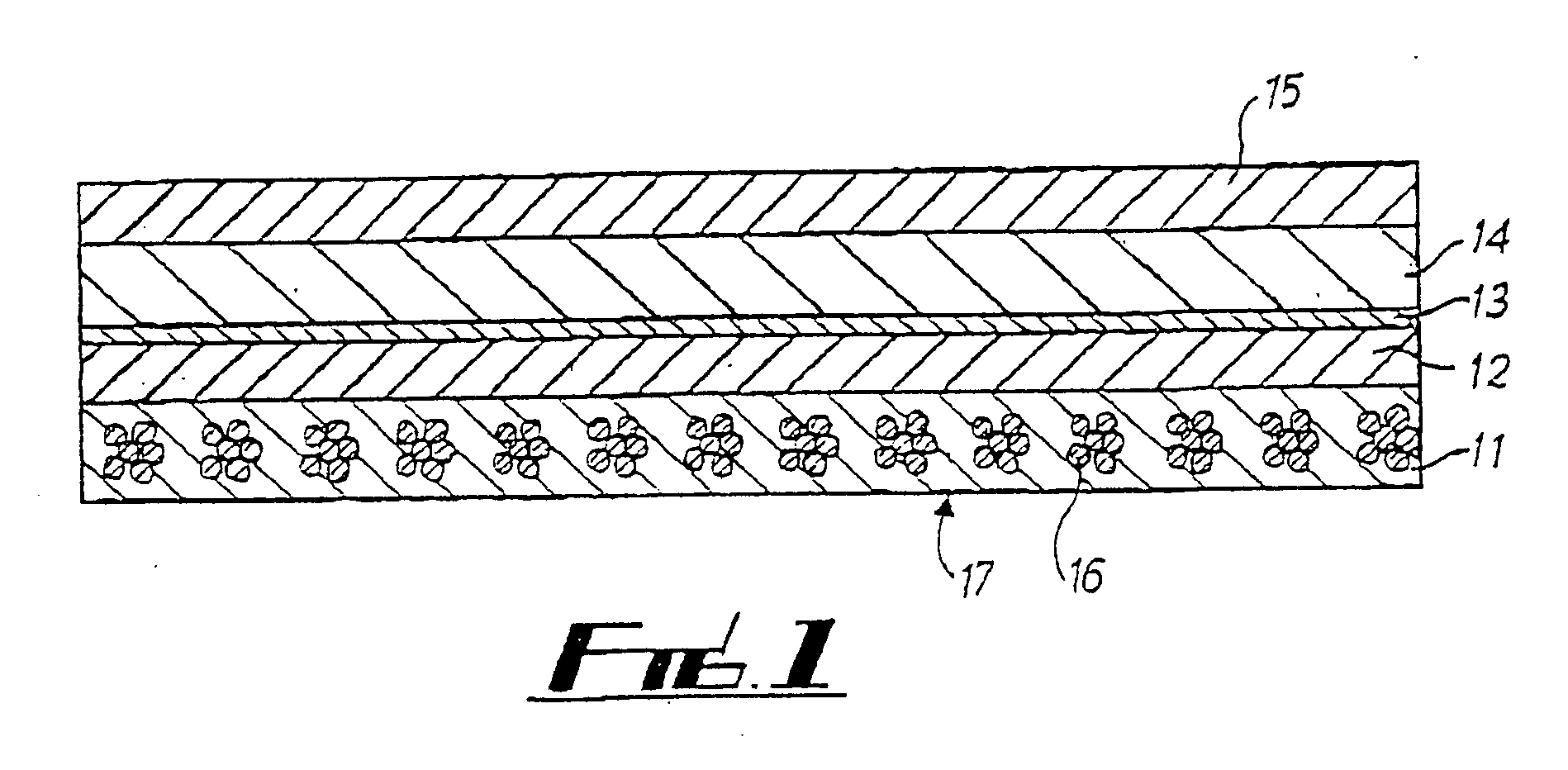
[0046] Referring to FIG. 1, a transfer and smoothing belt 17 for use in the press section of a paper machine includes an endless loop having five layers 11-15.

[0047] The supporting layer 11, includes spirally wound machine direction yarns 16 into which batt has been needled to hold the yarns 16 in position. In this embodiment the machine direction yarns include three pairs of yarns twisted together.

[0048] The second layer 12, located on layer 11, itself includes two individual layers of thermoplastic polyurethane each having a weight of 400 g / m2 and being 0.4 mm thick. On heating these two polyurethane layers, a single homogeneous layer is formed which bonds and partially impregnates the md supporting fabric 11 and the adjacent upper cd supporting layer 13.

[0049] Layer 13 includes a quasi non-woven structure made up of multifilament, cross-machine direction yarns and extremely fine machine direction yarns, for loosely holding the cross-machine direction yarns in position. This la...


PUM


Abstract

A paper machine belt that includes a cross-machine direction supporting layer providing strength in the cross-machine direction and at least two additional layers. The two additional layers include polymeric material and at least one of the additional layers that includes the polymeric material is positioned on one side of the cross-machine direction supporting layer and at least another of the additional layers that includes the polymeric material is positioned on an opposite side of the cross-machine direction supporting layer. The cross-machine direction supporting layer substantially includes cross-machine direction yarns loosely bound together with very fine machine-direction yarns. A ratio of mass of the cross-machine direction yarns to the machine direction yarns being at least 160:1, and mass of the polymeric material of the additional layer on the one side of the cross-machine direction supporting layer is substantially the same as a mass of the polymeric material of the additional layer that is provided on the opposite side of the cross-machine direction supporting layer.

Description

CROSS-REFERENCE TO RELATED APPLICATIONS [0001] The present application is a Continuation in Part of International Application No. PCT / GB03 / 00830, filed Feb. 24, 2003, and claims priority of Great Britain Patent Application No. 0204310.7, filed on Feb. 23, 2002. Moreover, the disclosure of International Patent Application No. PCT / GB03 / 00830, filed Feb. 24, 2003, and International Patent Application No. PCT / GB03 / 00824 filed Feb. 24, 2003 are expressly incorporated by reference herein in their entireties. BACKGROUND OF THE INVENTION [0002] 1. Field of the Invention [0003] The present invention relates to paper machine process belts and particularly, but not exclusively, to belts for transferring and / or smoothing the paper web within, to and / or from a press section of a paper machine. [0004] 2. Discussion of Background Information [0005] Transfer belts are used for carrying a paper web through a portion of a paper machine so as to eliminate open draws in which the paper web is unsupport...

Claims


Application Information

Patent Timeline
IPC IPC(8): D04B9/12D21F1/00D21F7/08
CPCD21F1/0036D21F7/086D21F7/083
Inventor KARLSSON, KJELL ANDERSLIDAR, VAINO PER-OLA
Owner VOTH FABRICS PATENT GMBH
Learn More